Liu Changqing, Huang Wenjun, Zhan Yuan, Zhejiang University
Keywords: PowerPC hardware platform; vehicle communication; global positioning system; special short-range communication
1 Overview
With the increasing traffic volume in cities and the increase of traffic congestion, the intelligent transportation system has received extensive attention. Intelligent transportation system is mainly composed of vehicle control center, transmission channel and vehicle-mounted communication system. How to improve the speed and reliability of real-time communication and real-time communication becomes the core of intelligent transportation system design. Vehicle communication technologies mainly include Dedicated Short Range Communication (DSRC), Wireless Fidelity (WiFi), and Cellular technology. WiFi technology data transmission rate is high but the communication distance is shorter than 1O0 m, and the link setup delay is long in seconds. The cellular network technology has a long communication distance, but the link establishment delay is a second long, and the provided bandwidth is very limited, and the coverage cost is relatively expensive. Therefore, the application of the above two technologies has great limitations. The United States, Japan, Europe and other countries have developed DSRC communication protocols for the intelligent transportation field. Among them, the WAVE (Wireless Access in Vehicular Environment)/DSRC (also known as DSRC) communication protocol in the United States is the most complete and the communication rate is up to 27 Mb / s, distance 1 km, link establishment time is shorter than 50 ms, in addition there are advantages of short packet transmission delay, support for on-vehicle communication within 500 km / h and so on.
This article uses WAVE/DSRC technology to design a high-speed, highly reliable, low-latency vehicle-mounted communication system. Due to the large amount of data in the DSRC protocol, the high speed, short delay and high network communication requirements of the vehicle-based communication system, the main controller hardware platform of this system adopts the superior processing performance and network communication performance based on the PowerPC architecture. MPC8377 processor. By transplanting the embedded Linux operating system to build the software platform, since the MPC8377 does not have an integrated LCD controller, the system uses the EP9315 of the ARM9 series from Cirrus Logic as the slave controller to implement the LCD touch screen display function.
2 System Framework
The frame of the on-board communication system is shown by a dashed box in Fig. 1, which is composed of a Road Said Unit (RSU) and an On Board Unit (OBU). System communication includes vehicle-to-road communication and vehicle-to-vehicle communication. For convenience, they are collectively referred to as onboard communication. The on-board unit OBU collects status information such as GPS positioning information, fuel door detection, and status information of the key input when the driver encounters a fault or dangerous road, and sends this information to the RSU on the roadside unit in real time by the DSRC module. The control center communicates data.

Figure 1 Vehicle Communication System Framework
In addition, the OBU sends information such as faults and dangerous roads to other OBUs in the same RSU service area. The RSU sends information such as the electronic map, road conditions, and schedule returned by the control center to each OBU through the DSRC module, and can display the electronic maps, scheduling, and other information of the nearby area in real time on the OBU touch screen. Drivers can select the optimal route based on electronic maps and fault conditions such as road conditions and scheduling information, avoid traffic jams or dangerous areas, ease traffic congestion, and improve the safety of transportation.
3 system hardware design
The OBU hardware structure of the onboard unit is shown in Figure 2. The roadside unit RSU hardware structure only contains DDR, NORFlash, DSRC and Ethernet modules.
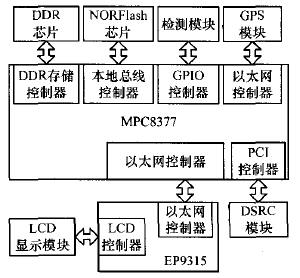
Figure 2 onboard unit hardware structure
3.1 Memory Module
The MPC8377 integrates a DDR SDRAM controller supporting 64-bit data read/write, and an external 512 Mb/s DDR SDRAM memory chip for running system programs and user programs to ensure high-speed operation and sufficient memory space for the program. The local bus controller controls 8 memory blocks. The starting address of each memory block is freely selectable. Each memory block can be arbitrarily configured in a range of 32 KB to 4 GB without any overlap. NORFlash, SRAM, and NandFlash are supported. Control interface. The first memory block is configured as a NORFlash interface, and an external 8 Mb/s NORFlash chip is used to store the boot code, operating system, and application program data. When the system is powered on, the boot code is read from NORFlash to complete the basic initialization. After that, copy the main program to DDR SDRAM memory for operation.
3.2 LCD display module
The MPC8377 integrates two Ethernet controllers, all supporting 10 Mb/s, 100 Mb/s, and 1 000 Mb/s communication rates. One Ethernet interface is responsible for communicating with the slave controller EP9315. The master-slave controller chip only implements the media media access control (MAC) layer protocol of Ethernet and communicates with the external physical layer PHY chip RTL8211 at a rate of 100 Mb/s. The controller EP9315 integrates the LCD controller internally. The external LCD touch screen display module is used to display the received data information. At the same time, the occurrence of the driver key event is monitored in real time through the touch screen key interrupt. Similar to the host controller, the slave controller also needs to extend the 8 Mb/s NOR Flash to store the boot code, operating system, and other firmware. Unlike the OBU, the RSU does not include a slave controller display module and the RSU Ethernet interface is used to communicate with the control center.
3.3 GPS data receiving and processing module
The GPS module completes the extraction of the GPS positioning signal and the time synchronization data, records the GPS signals transmitted from the antenna unit, demodulates and filters the signals, and restores the navigation messages sent by the GPS satellites, finally obtaining the navigation positioning. Location, direction, time, and other data.
The GPS module uses the GP3SF2525W1 module commonly used in the market. The module adopts the RS232 communication protocol interface. It needs to convert the MPC8377 serial UART interface to the RS232 interface through the physical layer. The system can obtain the GPS positioning information in real time through the GP3SF2525W1 module.
3.4 DSRC data transceiver module
Compared to the OSI7 layer model of open system interconnection, the DSRC protocol has a 5-layer structure as shown in Figure 3: L1, L2, L3, L4, and L7. Among them, the data link layer L2 is composed of a logical link control sub-layer (LLC) and a MAC sub-layer. The lower part of the physical layer L1 and the MAC sub-layer uses the IEEE802.11p protocol in the wireless LAN protocol standard. This agreement specifies the communication frequency, speed, radiated power, signal modulation method, etc. The IEEE802.11p and above protocols were developed by the IEEE1609 Working Group for Wireless Access in the Vehicle Environment (WAVE). The part on the MAC sub-layer is the IEEE 1609.4 WAVE multi-channel operating protocol. It defines a MAC enhancement mechanism to provide multi-channel cooperation functions. The LLC layer and above of the network layer L3 and the transport layer L4 use the IEEE 1609.3 WAVE network service protocol, which defines the network transmission service and utilizes the IP protocol stack to achieve seamless integration with existing networks and introduces The new WSMP (WAVE Short Message Protocol) protocol is designed to improve the efficiency of upper-layer applications for the use of low-level devices and supports a series of standards for vehicle-to-vehicle and vehicle-to-road communications. The application layer L7 customizes various traffic service information as required by the user.
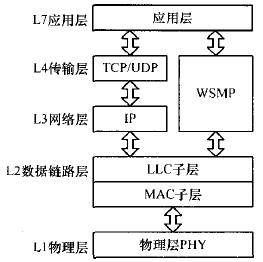
Figure 3 DSRC protocol hierarchy
This article uses Unex company's DCMA-86P2 module, this module is a mini PCI interface, need to convert the MPC8377 PCI interface into miniPCI interface to communicate with it.
In addition, the system also designed a multi-channel power output module to meet the power requirements of the hardware platform for different voltages and different power; multi-channel clock output module to provide different precision clock to each module; GPIO port detection module, connected through GPIO pins Various types of sensors detect various status information in the vehicle, such as fuel status, door status, and so on.
4 System Software Design
4.1 Linux System Migration
System software design is divided into MPC8377 master controller software design and EP9315 slave controller software design. Because the master-slave controller needs to complete multiple parallel tasks at the same time, the embedded Linux operating system is transplanted in order to solve the chaotic program structure caused by the operation of multiple tasks and reduce the difficulty of developing the software from the controller. Linux kernel is small, high efficiency, stable performance, good cutting ability, support graphical interface, adapt to a variety of CPU and multiple hardware platforms, kernel structure support in the network is very complete. The main control port is a Linux 2.6.32 kernel based on the PowerPC processor. The kernel integrates the WAVE protocol stack; the Linux 2.6.32 kernel for the EP9315 and the graphical interface are migrated from the controller. The Linux system can complete process management, memory management, file system, device control, and network implementation.
Linux system provides serial port, PCI, GPIO, LCD and other device drivers, which reduces the difficulty of system software development. Application layer developers operate the device by calling standard interfaces. Since the serial port, GPIO, and LCD driver are easier to implement, this article will not be described again. For the DSRC protocol, the hardware DSRC module only implements the physical layer and part of the MAC layer protocol, the driver needs to set up the PCI controller, configure the DSRC module through the PCI interface, including initialization, set send and receive operations, interrupt handling, etc. The protocol is implemented by the Linux kernel. Finally, Linux provides the Socket API standard interface to the application layer users. The user invokes the standard interface to implement the corresponding operation according to the specific application.
4.2 Controller Tasks
According to the function, the main controller system software is divided into four major modules: read the serial port task, DSRC task, GPIO detection task, and Ethernet data transceiving task, as shown in FIG. 4 .

Figure 4 master inverted software module
(1) Reading the serial port task periodically reads the GPS data received by the serial port and places the data in a fixed buffer for reading by the DSRC task.
(2) On one hand, the DSRC task periodically reads the GPS positioning data read from the serial port task and abnormal data generated due to I/O-induced interrupts, and packages it into a DSRC fixed-format data packet, that is, a WSMP data packet, and sends it to the RSU, on the other hand, receives WSMP packets sent by the RSU, including electronic maps, traffic conditions, and vehicle conditions. In addition, when the Ethernet receives a packet such as a risk of failure, the task is also responsible for sending the failed packet to other OBUs and RSUs in the same RSU range.
(3) Ethernet data transceiving task The electronic maps, road conditions and other data acquired by DSRC tasks are sent to the slave controller in the form of Ethernet packets, such as UDP, and are received in real time by the slave controller. The risk of failure and other data packets.
(4) The GPIO detection task periodically checks the I/O pin level status, including the oil amount and door detection. If an exception occurs, it triggers an interrupt to initiate a DSRC task and sends an appropriate exception packet to notify the RSU. At the same time, the controller can also change the level of the I/O pin to control this task.
The function of the slave controller is relatively simple. The introduction of the Linux operating system mainly performs LCD display tasks, key processing tasks, and Ethernet data transceiving tasks. The LCD display task is responsible for displaying the data received by the Ethernet on the screen. When a key occurs, it triggers an interrupt to send data packets such as an Ethernet failure to inform the host controller. The RSU RSU implements only the functions of DSRC tasks.
5 system testing
The system prototype developed five OBUs and one set of RSUs and placed them within 1 km. The two Ethernet interfaces of the OBU were used to connect slave controllers and personal computers, respectively, and the RSU Ethernet interface was connected to the computers. After the system is started, six computers enter the RSU and OBU Linux systems respectively by remote login. On the computer side, cross-compile the applications required for testing, and download the compiled executables to the RSU and OBU. Set the RSU to continuously send WSMP packets to the OBU through the DSRC module. The communication rate measured in different modulation modes is shown in Figure 5. From the test results, the system's communication rate is as high as 8.8 Mb/s.
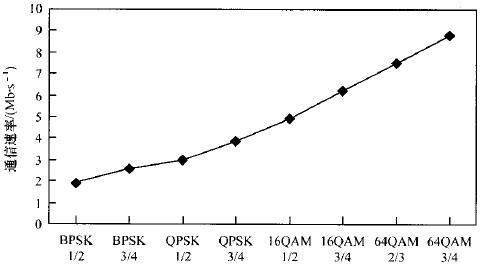
Figure 5 DSRC communication rates in different modulation modes
The WSMP data packets are sent from the RSU to each OBU, and the OBU responds to the same WSMP data packet immediately after receiving it, and then performs data packet sending delay and packet loss test. When the data packet size is 1200 Byte, the measured delay time in different modulation modes is shown in Figure 6. It can be seen that choosing the proper modulation mode can make the delay time as 50 ms, and the system has the characteristics of low delay. The RSU sends 1000 packets to each OBU. The number of response packets on the RSU is 5,000. No packet loss occurs.
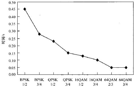
Figure 6 Packet transmission delay time in different modulation modes
Because the prototype OBU is too few and packet loss does not occur, NCTUns 6.0 network simulation software is used to test the packet loss rate. The simulation results are shown in Figure 7. It can be seen that when the number of vehicles in the same RSU service reaches 30, the packet loss rate of a single vehicle is less than 1%, and the system has high reliability.
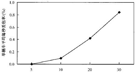
Figure 7 Average packet loss per second per vehicle
In addition, the OBU serial port received GPS data, abnormal touch screen buttons, I/O pin abnormalities, and LCD display functions. The results showed that each module can achieve corresponding functions.
6 Conclusion
This text combines PowerPC with embedded Linux operating system, has developed the main control module of the vehicle communication system, completed the design of display slave module through ARM9 to set up Linux. The test results show that the system can not only achieve basic functions such as GPS data acquisition and DSRC data transmission and reception, but also has the characteristics of high efficiency, reliability, and low delay, and has great practical value. The next step will be to study the RSU and multiple OBU networking technologies, as well as the communication technologies between the RSU and the control center, to form a complete, low-cost, easy-to-deploy intelligent transportation system.
Thermal Relay is used to protect AC three-phase asynchronous motor/electric motor against overload and open phase. Korlen electrical appliances produce thermal relay switch in wholesale,being a good thermal overload relay suppliers from china. We also offers Manual Motor Startor , AC Contactor, led light, Circuit Breaker etc.
Thermal Relay,Latching Relay,Reed Relay,Polarized Relay
Wenzhou Korlen Electric Appliances Co., Ltd. , https://www.zjaccontactor.com