The fault indicator is a device for overhead and underground distribution cables that detects and indicates fault conditions. For power companies, this device that continuously monitors the condition of power lines has always been a good helper for grid maintenance. As wireless communication and energy harvesting technologies become more sophisticated, the integration of fault indicators for both technologies further simplifies maintenance.
For grid operators, the Fault Indicator can be said to be a good helper for monitoring the condition of power cables and reducing the cost of maintenance. This type of installation is installed on overhead wires or underground power transmission cables. The typical appearance is usually shown in Figure 1.
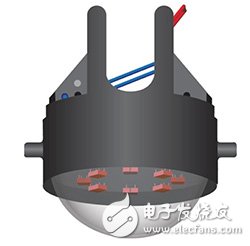
Figure 1 Example of an overhead fault indicator
There is a light-emitting diode (LED) at the bottom of the fault indicator. When an over-current condition occurs, the LED will light up, allowing maintenance personnel to see the fault from a distance and determine the fault point, greatly reducing the time required to find the fault. The work of the engineers has become much easier. After the fault indicator is properly installed, information can be displayed to identify faulty segments in the network, which helps reduce operating costs while reducing service disruption. In addition, the unit helps to avoid dangerous troubleshooting procedures, improve safety and reduce the chance of equipment damage.
Fault indicator intelligent trend shapingSince such devices are usually installed on utility poles or underground cable ducts and are mainly powered by batteries, such systems must operate at very low power consumption, otherwise power companies must often send people to change batteries, instead increasing The cost of grid maintenance. In addition, with the rise of concepts such as the Internet of Things (IoT) and smart cities, fault indicators have become more "smart."
Intelligent fault indicators often also have wireless communication capabilities so that maintenance personnel can remotely receive signals from a faulty indicator mounted on a utility pole or buried underground through a handheld device, without having to climb a pole or drill underground. If the fault indicator supports long-distance networking technologies such as Sub-GHz, an intelligent fault indication system (Figure 2) can be constructed to allow power maintenance personnel to monitor the status of the entire regional power grid directly from the central.
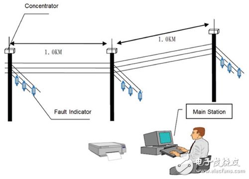
Figure 2 Intelligent Fault Indicator System
Referring to Fig. 2, the fault indicator is installed at the wiring of the overhead wire network, and the temperature measurement data and the current in the power transmission line are wirelessly transmitted to the remote terminal device installed on the utility pole. Remote Terminal Units (RTUs) RTUs use GSM modems to transmit data to mobile networks, and then relay real-time information to the main workstations. The main workstations can also control and perform diagnostics through the same data path. For underground cables, the fault indicator is connected to the RTU via a wired network such as RS-485.
The intelligent fault indicator is also known as the "networking" fault indicator because it can be connected to the main workstation at any time. There are several advantages to connecting to a main workstation at any time. First, the fault condition can be remotely monitored from the main workstation, and the power company personnel do not have to go to the site in person in order to find the fault location. The intelligent fault indicator also continuously monitors temperature and current, allowing the main station's controller to know the status of the transmission and distribution network in real time. With this extra information, utilities can quickly identify fault locations, minimize power outages, and even take action before a fault occurs. In addition, the main workstation personnel can periodically perform diagnostics on the fault indicator to ensure that everything is working properly.
Since the fault indicator is battery powered and mounted on the wire, the primary system must operate at very low power consumption. How to choose the right microcontroller is the most important decision. In addition to traditional control-oriented features, the MCU's highly integrated analog circuitry also helps to reduce the size of the external analog front-end circuitry while significantly reducing overall system power consumption.
In other words, the quality of the fault indicator depends mostly on the MCU selected for the fault indicator. This article will use Texas Instruments' MSP430 microcontroller as an example to illustrate the advantages of low-power MCUs with ferroelectric random access memory (FRAM) for fault indicator applications. In addition, this article will also introduce energy harvesting and wireless communication technologies suitable for such applications.
Highly integrated MCU simplifies basic functional implementationSee Figure 3 for the intelligent fault indicator function block diagram using the TI MSP430 FRAM microcontroller. The current Sensor will generate an analog voltage that is proportional to the current of the wire. The voltage signal is regulated (amplified and filtered) by an operational amplifier, and the output of the operational amplifier is sampled by an analog-to-digital converter (ADC) to the MCU, which then performs data analysis on the digital stream of the ADC. As shown in Figure 3, the output of the op amp is directed to the comparator of the MCU. If the input exceeds a preset threshold, the comparator will generate a flag and transmit it to the microcontroller's CPU.
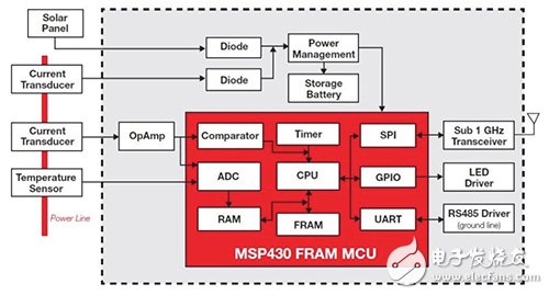
Figure 3 Intelligent Fault Indicator Functional Block Diagram with MSP430 FRAM MCU
The analysis of the electrical current measurement can be performed from the time domain or the frequency domain. If the current waveform of the wire is far from the sine wave and the irregularity of the waveform has formed a concern, performing spectrum analysis at this time will become an easy way to evaluate the state of the line.
If the maximum frequency required is 100 Hz, the line current must be sampled every five milliseconds. The 64-point Fast Fourier Transform (FFT) provides a spectrum of 0 ∼ 100 Hz with a resolution of 3 Hz. The MSP430 microcontroller CPU performs an FFT at a frequency of 16 MHz, which takes about one millisecond. In order to eliminate aliasing caused by high frequency noise, the low pass filter must be implemented together with the operational amplifier. The results of the spectrum analysis will be used to determine if the wire current is normal.
Wire temperature is also important information for the sound condition of Shaoguan wire. The output of the temperature sensor is typically voltage and can be sensed directly by the ADC on the MCU.
Once processed, the fault indicator transmits the output data to the RTU via a wireless link. In order to achieve the required transmission distance and minimize power consumption, Sub-GHz connection technology is usually used. If the fault indicator is installed on ground, the RS485 interface can be used, but the MCU may have to encrypt the data according to the security requirements of the system. The traditional LED lights up when the fault indicator detects a fault condition.
Resolver is a kind of commonly used angle detection component, because of its simple structure, reliable operation, and its accuracy can meet the general detection requirements

Resolver,Encoder Troubleshooting Resolver,Custom Resolver,Online Resolver
Yuheng Optics Co., Ltd.(Changchun) , https://www.yhencoder.com