Weighted analysis of 3bits phase quantized digital frequency storage signal
Abstract: This paper theoretically analyzes the signal weighting in the DRFM technique, and derives the optimal weight coefficient for suppressing low-order harmonics. The simulation results show that: after weighting with the best weight coefficients, the low-order harmonics are effectively suppressed, which provides a theoretical basis and engineering implementation method for the engineering to implement DRFM technology to suppress parasitic signals.
Keywords: signal processing; DRFM technique; optimal phase weighting; harmonic suppression
1. Introduction The DRFM technology is a technology developed along with the higher requirements of the new generation of electronic warfare for electronic interference capabilities. It has the ability to coherently capture and copy pulses, providing an effective means for jamming PD and pulse pressure new system radar . With the enhancement of radar anti-jamming capability, there are still some technical difficulties in the application of DRFM technology. Among them, the parasitic signal is a problem that cannot be ignored: on the one hand, it reduces the effective radiated power of the jammer; on the other hand, it may become a beacon for radar detection and detection targets.
There are three main sources of DRFM parasitic signals: local oscillator leakage, image response, harmonics and cross modulation. For local oscillator leakage, an up-conversion single-sideband modulation mixer can be used for suppression; for the image response, two-channel orthogonal mixing, filtering, baseband amplification, and A / D conversion can be selected to solve. This article mainly theoretically analyzes the use of weighted methods to suppress the harmonics generated by quantization, and carries out corresponding calculation and simulation.
2. Theoretical analysis of 3 bits phase weighting Basic principle and analysis of phase quantization frequency storage First, phase quantization frequency storage needs to convert analog intermediate frequency signal into digital signal, that is, quantization. If the sinusoidal signal is quantized into a 1-bit rectangular wave, the two levels represent the positive and negative half-cycles of the sinusoidal signal respectively, which is called 1-bit quantization. The time domain expression and the Fourier series expansion expression are respectively
Nbits phase quantization frequency storage is to divide one cycle of a 1-bit quantized sinusoidal signal into 2N phase intervals, and then store the phase codes generated by the N phase intervals, and add them at a certain phase interval. The unweighted expression of Nbits phase quantization frequency storage is
By simulating (2), the normalized energy of the 3rd, 5th, and 7th harmonics changes with the number of quantization digits, as shown in Figure 1. It is easy to derive from a simple mathematical derivation: 2 bits phase quantization and weighting cannot change the energy ratio of each harmonic to the fundamental wave. It can be seen from Figure 1 that although the quantization of more than 4 bits is greatly increased in complexity, it does not significantly improve the harmonic energy. On the other hand, in engineering, we mainly consider the suppression of low-order harmonics. If the low-bit phase quantization can better suppress the 3rd and 5th harmonics by amplitude weighting, it is very practical to discuss it.

The output signal of 3 bits digital frequency storage is composed of 4 1 bit phase digital frequency storage output signals with a one-eighth cycle delay between each other, so the output signal of 3 bits phase digital frequency storage can be regarded as two The sum of the eighth-cycle delayed quadrature frequency storage output signals.
2. Derivation and analysis of weighting formula 3 bits phase quantized weighted expression is
Among them, a, b, c and d are the weighting coefficients of each phase quantization of 3 bits.
The Fourier series expansion of the above formula is:
Obviously, the even term in the above formula is zero, that is, the even harmonics are zero. The case where n is an odd number is discussed below:
When n = 1, the energy of the fundamental wave is

From formula (4) and formula (5), we know that no matter what the values ​​of a, b, c, and d are, 8m ± 1 (m∈N, m = 1, 2, 3, ...) subharmonics and fundamental energy The ratio is constant, so by changing the weight coefficient, the ratio of harmonic to fundamental energy can be changed to n = (8m-4) ± 1 (m∈N, m = 1, 2, 3, ...) .
In summary, the following conclusions can be drawn:
(1) Regardless of the values ​​of a, b, c, and d, even harmonic energy is zero, n = 8m ± 1 (m∈N, m = 1, 2, 3, ...) The ratio of wave energy is constant; 
(3) It is easy to derive from (2): if the ratio of a and c is fixed, the ratio of any two quantities of a, b, c and d is fixed, and the ratio of harmonic energy to fundamental energy is determined by a and b , The ratio of c and d is determined, so in the calculation and simulation process, we only need to simulate and compare the harmonic power under different a: c values.
Third, the 3-bit phase quantization weighted simulation The above analysis considers only the ideal quantization signal waveform, that is, the parasitic signal power distribution generated by the completely symmetric quantization signal waveform. In actual engineering, when sampling a sine wave, there is no fixed phase relationship between the sampled signal and the baseband signal, coupled with the influence of the circuit, it is impossible to obtain a perfectly symmetrical ideal quantized waveform. Therefore, in the following calculation and simulation process, in addition to the fundamental wave and harmonics, there are spurious signals at other frequencies. The presence of spurious signals may make the simulation results and the theoretical analysis have certain errors.
Sine signal X (t) = Emsin (2Ï€ft) with frequency f = 30 MHz and pulse width of 10 / f is sampled and quantized. The number of sampling points is 2 048 points. FFT transformation is performed on the normalized signal to obtain the signal spectrum diagram and the parasitic signal power variation curve with a: c value before and after phase quantization and weighting, as shown in FIG.
4. Conclusion analysis and simulation results show that: the low-order harmonics of the quantized signal can be greatly suppressed by weighting; the asymmetry of the signal leads to the appearance of spurious signals, so that the ratio of a and c has a selectable optimal value.
From Figure 2 (a) ~ (d), it can be intuitively obtained that the suppression of the 3rd and 5th harmonics after weighting is at least 10 dB higher than that without weighting, and a: c is the 3rd and 5th harmonics when it is 0.414 The wave suppression effect is significantly better than other ratios; Figure 2 (e) further illustrates that the optimal ratio of a and c is 0.414, and under this ratio, the relationship between the optimal weight coefficients for engineering realization is derived as: (b = c): (a = d) = 2.415.
In summary, through analysis, we have obtained the optimal weight coefficient relationship for suppressing harmonics in parasitic signals; through calculation and simulation, we have confirmed the analysis results and provided a theoretical basis for the suppression of parasitic signals And engineering implementation.
references
[1] Cui Bingfu. Performance and interference effect of phase digital frequency storage ï¼»Jï¼½. Electronic countermeasure technology, 1999, (6).
[2] Ding Yumei, Gao Xiquan, Peng Xueyu. Digital signal processing [M]. Xidian University Press, 1999.
[3] Zhou Guofu, Ji Guoliang. Digital radio frequency memory and its application in electronic warfare system [C]. 1990.
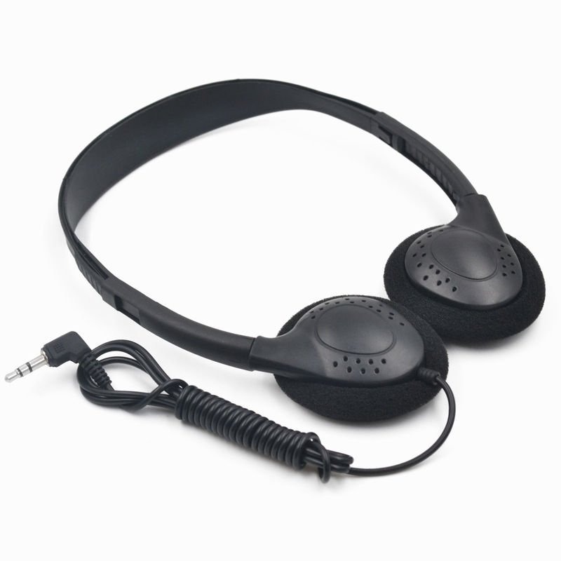
Aviation headphones are used in airplanes, cars, subways, etc., to facilitate passengers to listen to audio and watch videos to enjoy a pleasant journey.
The aviation earphones are mostly disposable, so the structure is extremely simple, the shape is relatively ordinary, the materials are small, and the annual usage is very large. The number of inquiry can reach several million or even tens of millions, so the cost is very cheap. earphones can cost as little as 10-15 cents. Therefore, they are disposed of as garbage after used, and passengers could take it away for personal use.
Styles can be divided into on ear headphones and in ear earphones.
Functional difference: power, impedance, and sensitivity etc. are also different. Airplane Headphone is mainly customized according to the equipment, place and user used. For example, 1 customer might require 300 ohms impedances , and other customers may need 32 ohms. For adults, the sensitivity may reach 100DB or more.To children, the sensitivity may be around 85-90 DB.
In addition, aviation headphones are not all disposable ones. Some first-class cabins need to be equipped with headphones with good noise reduction, sound quality and functions. So the price will be much more expensive.

Airline Headphones,Airline Earphones,Airplane Headphones,Airline Noise Cancelling Headphones
Shenzhen Linx Technology Co., Ltd. , https://www.linxheadphone.com