TV basics
The goals of the broadcast television system (Figure 07-02-1) are:
Use bandwidth efficiently;
High ratings.
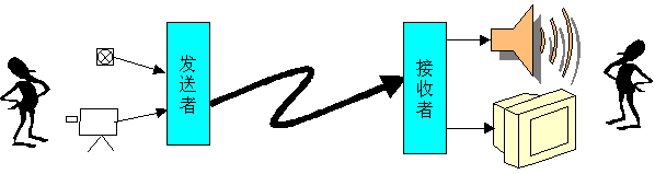
Figure 07-02-1 Broadcasting and Television System
The TV system is composed of three parts: the sending end, the channel and the receiving end. The basic block diagram is shown in the figure.
![]()
Figure 07-02-2 The basic block diagram of the TV system
Television systems can transmit not only sound but also images. The sending end uses a camera device to perform optical-electrical conversion, and converts the optical image into a corresponding electrical signal. A signal channel is a path for transmitting electrical signals, which can be wireless or wired. The receiving end uses the imaging device to perform electrical-optical conversion of the image electrical signal transmitted through the channel, restore the optical signal, and reproduce the image.
One. Sequential transmission of images
1. Pixel
A black and white still image is composed of many small units, and the small units that make up the image are called pixels (Figure 07-02-3). This is how the fax pictures in the newspaper are constructed. For the observer, each pixel has its optical characteristics and spatial position, and changes with time. Any pixel P in the scene image can be expressed by eight physical quantities, namely
P = f (x, y, z, L, H, S, R, t)
Among them, (x, y, z) represents the spatial position of the pixel, L, H, S respectively represent the brightness, hue and saturation of the pixel, R is the resolution of the image (each pixel area accounts for the total area of ​​the scene Ratio), and t is the time when the pixel produces the above physical quantity. For the current color TV system, since it can only express the two-dimensional plane information of the image instead of the three-dimensional stereoscopic information, it is impossible to reflect all eight physical quantities.
Obviously, the more pixels that an image decomposes, the clearer the image. Usually, an image of a 35mm film film has about one million pixels, and a TV image has about 400,000 pixels. For a color image on a fluorescent screen, it is composed of many color pixels. For a color TV, a color pixel is composed of red, green, and blue dots.
Figure 07-02-3 An image is composed of many pixels
In a television system, the image is first decomposed into pixels at the sending end, and then the brightness information (or color information) of these pixels is converted into electrical information for transmission, and then the pixels are combined into an image at the receiving end.
2. Sequential transmission of still images
How is the pixel information of the image transmitted? Obviously, the simultaneous transmission system is unrealistic. The so-called simultaneous system is to transmit all the pixel information of an image to the receiving end through their respective signal channels at the same time. This method is not easy to implement because there are too many signal channels required for the simultaneous transmission mode.
In fact, the sequential transmission system is often used in television technology, that is, the brightness information of each pixel on the image is converted into a corresponding electrical signal one by one in a certain time sequence at the sending end, and then transmitted through the same channel in turn at the receiving end In the same order, the electrical signals of each pixel are converted into light spots of different brightness at the corresponding positions of the TV screen. As long as the speed of this sequential transmission is fast enough, then due to the visual inertia of the human eye and the afterglow characteristics of the luminescent material, the entire image will feel illuminated at the same time. A television system formed by this method of sequentially transmitting image pixels is called a sequential transmission system, as shown in Figure 07-02-4.
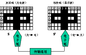
Figure 07-02-4 Schematic diagram of sequential transmission television system
It can be seen from Figure 07-02-4, assuming that the sending end is a photoelectric panel composed of many photocells, and the receiving end is a display panel composed of many light bulbs, and the two ends are connected by a signal channel to form a TV transmission system. If the image of "middle" is transmitted, the electronic pen S starts to scan the photoelectric panel in order from the upper left corner of the image, decomposes the pixels while completing the photo-electric conversion, and sequentially transmits the electrical signals of each pixel to the electronic pen S ', S through a channel 'Sweep the display panel in the same order, complete the electro-optical conversion while recombining pixels, and reproduce the image. The electronic pens S and S 'at the sending end and the receiving end must work synchronously, that is, the scanning positions of the two electronic pens S and S' correspond to each other, and the scanning speed is the same, so that the reproduced image is accurate. Of course, the conversion speed of the electronic pen should be fast enough to use the visual inertia of the human eye to see a complete image.
In fact, in the TV system, the conversion function of the electronic pens S and S 'is completed by electron beam scanning.
3. Sequential transmission of moving images
Most of the images transmitted by modern TV systems are moving images. How to transmit moving images has become an important issue in sequential image transmission systems. The way the movie is shown inspires people. When showing a movie, as long as 24 frames per second, time-related still pictures with similar contents are displayed. Due to the visual inertia of the human eye, the feeling of the previous image has not disappeared, the latter image has arrived, and the result makes people feel The image is continuously moving.
In the same way, TV can also use a method similar to that of movies to decompose moving images into still images one after another. When the transmission speed is fast enough, human eyes will feel continuous moving images. China stipulates that the transmission speed of television images is 25 frames per second.
It can be known from the film practice that although images can be transmitted continuously up to 24 frames per second, continuous moving images can be obtained, but there is a sense of light flicker that causes fatigue to human eyes. In order to overcome this phenomenon, the film machine needs to block the light once when projecting an image, so that each image is projected twice in succession. In this way, there are actually 48 images per second for the human eye. The TV system is also facing the same problem. It uses interlaced scanning technology to transmit each image in two fields, so that the TV can actually transmit 50 times per second, thereby effectively overcoming the light flicker phenomenon.
two. scanning
Television technology uses the photoelectric conversion principle to realize the conversion of optical images into television signals. This conversion process is usually completed in the camera. When the subject is imaged on the photoconductive layer of the camera tube through the camera lens, different points on the photoelectric target excite different numbers of photoelectrons with different illuminances, thereby causing different additional photoconductors to produce different potential fluctuations, forming a photo image Corresponding electrical image.
Using the visual inertia of the human eye, the physical quantities representing the pixels in the image can be transmitted one by one in a certain order at the sending end, and the original image is reproduced according to the same rules at the receiving end. As long as this sequence is carried out fast enough, the human eye will feel the image shining at the same time. In television technology, this established law of transmitting images is called scanning. As shown in Figure 07-02-5, the electrical image formed in the photoconductive layer of the camera tube turns on each point sequentially under the scanning of the electron beam, and continuously converts their brightness changes into electrical signals; After the electrical signal is transmitted through a single channel, the fluorescent screen with electro-optic conversion characteristics is scanned with an electron beam to convert the electrical signal into an optical image.
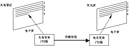
Figure 07-02-5 Scanning principle of TV system
Under normal circumstances, the electric vacuum cameras and imaging devices commonly used in television systems currently use electron beam scanning to achieve photoelectric and electro-optic conversion; and with the use of CCD cameras and flat panel display devices, various pulse digital circuits are used. The above conversion can be achieved. Figure 07-02-6 is a schematic diagram of the scanning processing of a cathode ray tube (CRT), in which the video signal is composed of luma and chroma signal components, and the component video sends out the luma and chroma signals, respectively.
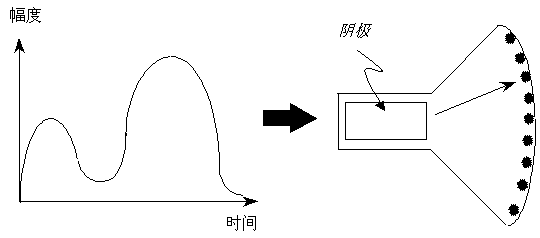
Figure 07-02-6 Schematic diagram of cathode ray tube (CRT) scanning process
There are two types of scanning methods: progressive scanning and interlaced scanning.
The method of sequentially scanning the electron beam from left to right and from top to bottom is called progressive scanning. The linear bright spot trajectory formed by the sequential scanning of the electron beam is called a raster, and the schematic diagram of the raster formed by progressive scanning is shown in Figure 07-02-7.
(1) Line scanning: The scanning of the electron beam in the horizontal direction is called line scanning. The scan from left to right is called line scan forward, or line scan for short, as shown by the solid line in Figure 07-02-7 (a). Scanning from right to left is called line scan inverse, or line retrace for short. As shown by the dotted line in 07-02-7 (a). The line scan has a long forward travel time and a short reverse travel time. Obviously, for each image, the more scanning lines, the higher the resolution of the image, the finer the image; but at the same time, the wider the TV signal bandwidth, the higher the channel requirements.
(2) Frame scanning: The scanning of the electron beam in the vertical direction is called frame scanning. The scan from top to bottom is called frame scan forward, referred to as frame forward scan, and the scan from bottom to top is called frame scan reverse, referred to as frame retrace. Figure 07-02-7 (a) shows the scan trajectory of the frame scan forward, and Figure 07-02-7 (b) shows the retrace trajectory of the frame scan reverse. Similarly, the frame scan forward travel time is much greater than the frame scan reverse travel time.
In fact, the line scanning and the frame scanning are performed simultaneously, that is, the electron beam moves in the vertical direction L while scanning in the horizontal direction, then the movement trajectory of the electron beam is the combined motion of the horizontal and vertical directions. Since the scanning speed of the electron beam in the horizontal direction is much higher than that in the vertical direction, a horizontal bright line slightly obliquely downward is formed on the fluorescent screen, and hundreds of rows of densely scanned bright lines form a uniform grid-like light emitting surface, which is called Raster. One frame is a progressive scan.
|
|
(a) | (b) |

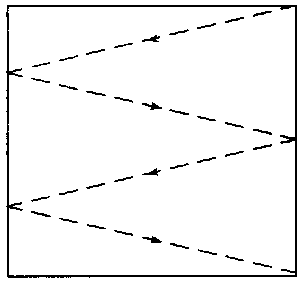
Figure 07-02-7 Schematic diagram of progressive scanning raster
The disadvantages of progressive scanning: to make the image continuous without flickering, it needs to change frames 50 times per second, that is, the frame frequency is 50Hz, but the bandwidth of the image signal is too wide, which complicates the TV equipment. In order to compress the bandwidth of the image signal and at the same time to overcome the flicker phenomenon, the interlaced scanning method has been proposed for the film technology. Current radio and television use interlaced scanning.
2. Interlaced scanning
Interlaced scanning is to divide a frame of image into two fields for scanning. The first field scans odd lines, which is called odd field, and the second field scans even lines, which is called even field. Odd and even field images are mosaiced together to form a complete image, as shown in Figure 07-02-8.

Figure 07-02-8 Schematic diagram of interlaced image reproduction
The interlaced raster is shown in Figure 07-02-9. After scanning the first line, the electron beam returns to the beginning of the third line and then scans, as shown in Figure 07-02-9 (a), and then at the fifth , 7, ..., line scan up to the last line. After scanning the odd lines, scan the even lines (Figure 07-02-9 (b)), so that a frame scan is completed (Figure 07-02-9 (c)). It can be seen from this that an interlaced image consists of two parts: one part is composed of odd lines, called an odd field, and the other part is composed of even lines, called an even field, which together form a frame on two occasions. Therefore, in interlaced scanning, whether it is a camera or a display, an image must be scanned twice to obtain a complete image (Figure 07-02-8).
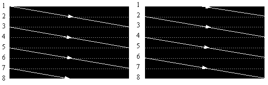
(A) Odd field (b) Even field

(C) An interlaced frame
Figure 07-02-9 Schematic diagram of interlaced scanning raster
In interlaced scanning, the number of lines scanned must be odd. As described above, one frame of picture is divided into two fields, the first field scans half of the total lines, and the second field scans the other half of the total lines. Interlaced scanning requires that the first field ends at half of the last line. No matter how the electron beam is folded back, it must return to the center of the top of the display screen, so that it can ensure that the adjacent second field scan is exactly embedded in the scan lines of the first field intermediate. It is for this reason that the total number of rows must be odd.
For interlaced scanning, in order to make the transmitted moving image feel continuous without flickering, it needs to scan 50 fields per second, that is, the field frequency is 50 Hz. While two fields are one frame, 25 frames per second are scanned, that is, the frame rate is 25 Hz, thereby reducing the frame rate, compressing the bandwidth of the image signal, and overcoming the flicker phenomenon.
The number of lines scanned per second is called line frequency fH; the number of fields scanned per second is called field frequency fc; the number of frames scanned per second is called frame frequency fF. fc and fF are two different concepts.
Both black-and-white TVs and color TVs use interlaced scanning, while computers generally use non-interlaced scanning when displaying images.
three. Blanking and synchronization
1. Blanking
In the TV system, the image signal is transmitted during the forward scan, and the image signal is not transmitted during the reverse trip. The retrace line appears on the fluorescent screen by the electron beam reverse scan, which will cause interference to the image of the forward path and affect the clarity of the image. Therefore, it is necessary to cut off the electron beam of the TV set during the reverse scanning of the line and field to eliminate the retrace line of the line and field, so as to realize blanking. The method is that the blanking signal is sent by the synchronous machine at the TV station to make the receiver picture tube turn off the electron beam during the line and field reverse scanning.
2. Synchronize
In the TV system, in order to make the image reproduced by the TV set exactly the same as the image taken by the camera, the electron beam scanning of the receiving end and the sending end must be synchronized. The so-called synchronization means that the frequency (fast and slow) of the scan at the receiving and sending ends is exactly the same as the phase (starting position) of the scan. If the receiving and sending end scans are not synchronized, the reproduced image is deformed or unstable. In severe cases, the image is chaotic and cannot be viewed normally.
In order to ensure the synchronization of line and field scanning at the receiving and transmitting ends, the synchronous machine of the TV station sends out line and field synchronization signals, so that the TV receiver accurately reproduces the image.
four. Camera and imaging
(1) Camera principle
The optical-electric conversion at the sending end is done by the camera tube. There are various forms of camera tubes. At present, black and white or color TV cameras widely use lead oxide (pbo) tubes with an internal photoelectric effect. Figure 07-02-10 is a schematic diagram of its structure. Its cylindrical glass casing mainly contains two parts: a photoelectric target and an electron gun. A deflection coil, a focusing coil and a correction coil are arranged outside the tube.
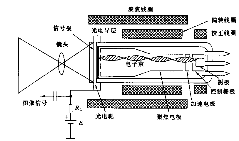
Figure 07-02-10 Camera tube
(1) Photoelectric target; a thin and transparent metal conductive film is coated on the inner wall of the glass screen in front of the camera tube as a light path and a signal output electrode. Behind the metal film is the photoelectric target. Its structure is shown in Figure 07- 02-11 (a). The photoelectric target is composed of three layers of semiconductor materials. The thicker layer in the middle is the lead oxide semiconductor (pbo), called the I layer, the layer scanned by the electron beam inside is the P-type semiconductor layer, and the layer exposed to light on the outside and in contact with the transparent metal film is the N-type semiconductor . Both the P layer and the N layer are much thinner than the I layer, so the photoelectric target of the pbo tube is actually equivalent to a photodiode, and its working performance is mainly determined by the I layer (pbo). Due to the photosensitive properties of semiconductors, when the intensity of the light shining on it changes, its equivalent resistance also changes.
(2) Electron gun: The electron gun is composed of a filament, cathode, control grid, accelerating pole, focusing pole, etc. which are covered in a vacuum glass tube. When a normal voltage is applied to each electrode, the electrons emitted by the cathode are accelerated and focused into a very thin electron beam on the photoelectric target by the acceleration electrode, focusing electrode, and high-voltage anode (mesh electrode). The electron beam is moved by the line and field deflection magnetic fields sheathed outside the tube, and moves from left to right along the target surface from top to bottom to pick up the signal.
(3) Image signal generation: The schematic diagram of the image signal generation circuit is shown in Figure 07-02-11 (b). When the image is imaged on the photoelectric target through the camera lens, corresponding to the bright spot of the image pixel, the conductivity of the photoconductive layer is high, the equivalent resistance is small, and the electron beam is scanned to Figure 07-02-10. "Bright spot", the current it forms in the loop is large, the voltage drop across the load resistance is large, and the output voltage is small. Conversely, corresponding to the dark spot of the image pixel, the corresponding equivalent resistance of the photoconductive layer is large. When the electron beam scans to the "dark spot", the current formed in the loop is small, the voltage drop across the load resistance is small, and the output The voltage is large. Obviously, the level of the image signal voltage output by the camera tube is inversely proportional to the brightness of the image, which is called a negative TV signal. By the way, if the voltage of the image signal is proportional to the brightness of the image, it is called a positive TV signal. As mentioned above, the camera tube converts the light and dark information of the pixels at each point of the image into electrical signals with voltage changes, and completes the photoelectric conversion.
|
|
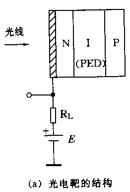
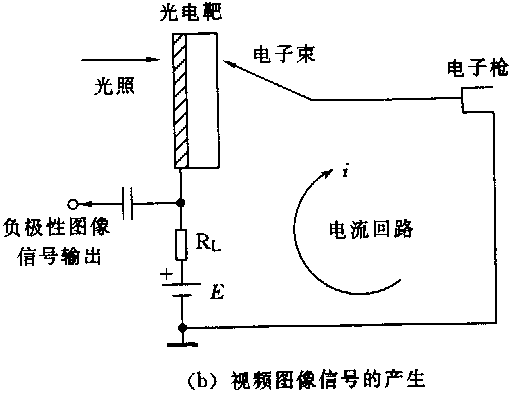
Fig. 07-02-11
Principle of three imaging
CRT is an important device to complete the electric-optical conversion at the receiving end. The schematic diagram of the picture tube is shown in Figure 07-02-12. It is composed of an electron gun and a fluorescent screen. The front end of the glass casing of the kinescope is a fluorescent screen, and the inner wall of the glass of the fluorescent screen is coated with a layer of phosphor powder, which can emit light when bombarded by an electron beam. The electron gun is composed of various metal electrodes. When an appropriate voltage is applied to each electrode, the cathode of the electron gun is baked by the filament to emit electrons, which are aggregated into a beam to bombard the fluorescent screen. The electron beam scans the fluorescent screen under the action of the magnetic field generated by the outer casing deflection coil.
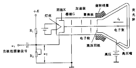
Figure 07-02-12 Schematic diagram of the picture tube
When the negative-polarity image signal is added to the cathode K, it can control the change of the grid cathode voltage, control the intensity of the electron beam current Ik, and thereby control the brightness of each point of the electron beam scanning the fluorescent screen, and restore the image on the fluorescent screen. If the image signal voltage applied to the cathode is higher, the grid cathode voltage becomes more negative, that is, the greater the negative voltage between the grid and the cathode, the weaker the electron beam current, and the darker the corresponding phosphor spot. Conversely, if the voltage of the image signal applied to the cathode is lower, the electron beam current is stronger, and the corresponding phosphor dot is brighter, which is exactly the same as the brightness and darkness of the corresponding pixel of the image at the sending end. The electron beam scans the entire fluorescent screen to form a complete image.
Fives. Gamma (g) correction
(1) The concept of gamma (g)
The photoelectric conversion characteristics of almost all CRT display devices, photographic films, and many electronic cameras in the real world are non-linear. The relationship between the output and input of these nonlinear components (for example, the relationship between the output voltage of the electronic camera and the light intensity in the scene, the relationship between the intensity of the light emitted by the CRT and the input voltage) can be expressed by a power function, its The general form is:
Output = (input) g
The g (gamma) in the formula is the exponent of the power function, which is used to measure the conversion characteristics of nonlinear components. This characteristic is called the power-law conversion characteristic. By convention, both "input" and "output" are scaled to between 0 and 1. Among them, 0 represents the black level, and 1 represents the highest level of the color component. For a particular component, one can measure the functional relationship between its input and output to find the value of g.
The actual image system is composed of multiple components, and there may be several non-linear components in these components. If all components have the conversion characteristic of a power function, then the transfer function of the entire system is a power function whose index g is equal to the product of g of all individual components. If the entire g = 1 of the image system, the output and input have a linear relationship. This means that the ratio of the intensity of any two image areas in the reproduced image is the same as the intensity of the two areas of the original scene, which seems to be the goal pursued by the image system: to reproduce the original scene truly. But the actual situation is not exactly like this.
When this regenerated image is viewed in a "bright environment", that is, an environment where the brightness of other white objects is almost the same as the brightness of the white part of the image, the system of g = 1 can indeed make the image look like the "original scene" "same. However, some images sometimes get better results when viewed in a "dark environment", which is the case for film projection and slide projection. In this case, the value of g is not equal to 1, and it is generally considered that g »1.5, the scene seen by the human perspective system seems to be the" original scene ". From this point of view, the g value of the projected slide is designed to be around 1.5 instead of 1.
There is also an environment called the "dim environment" of the intermediate environment, which is like other things in the room can be seen, but the brightness is darker than the white part of the image. This is the case for watching TV and computer room. In this case, it is generally considered that the reproduced image needs g »1.25 to look like an" original scene ".
(Two) g correction
All CRT display devices have power-law conversion characteristics, if the manufacturer does not specify, then its g value is approximately equal to 2.5. The user may be powerless to change the characteristics of the glowing phosphorescent material, so it is difficult to change its g value. In order to make the g value of the whole system close to the g value required for use, at least a nonlinear component that can provide g correction is needed to compensate the nonlinear characteristics of the CRT.
In all broadcast and television systems, g correction is done in the camera. The original NTSC television standard required the camera to have a power function of g = 1 / 2.2 = 0.45, and now the power function of g = 0.5 is adopted. The PAL and SECAM TV standards specify that the camera needs to have a power function of g = 1 / 2.80 = 0.36, but this value is already too small, so the actual camera is likely to be set to g = 0.45 or 0.5. The image obtained using this camera is corrected in advance. When the image is displayed on the CRT screen with g = 2.5, the screen image relative to the original scene g is approximately equal to 1.25. This value is suitable for viewing in "dark environment".
The past era was the "analog era", but now it has entered the "digital era", and the TV image entering the computer still has the correction of g = 0.5. Don't forget this. Although TVs with g-values ​​work very well in the digital age, especially images created in specific environments work in the same environment. However, when working in other environments, the displayed image often makes people look too bright or too dark, so g correction should be done under possible conditions.
Where to do g correction is a matter of concern to people. From acquiring an image, storing it as an image file, and reading out the image file until displaying the image on a certain type of display screen, at least 5 of these links can have non-linear conversion functions and can introduce g values. E.g:
| camera_gamma: g of the image sensor in the camera (usually g = 0.4 or 0.5) |
| encoding_gamma: The encoder introduces g when encoding image files |
| decoding_gamma: Introduce g when the decoder reads the image file |
| LUT_gamma: Introducing g in the image frame buffer lookup table |
| CRT_gamma: g of CRT (usually g = 2.5) |
In the digital image display system, since the image to be displayed is not necessarily the image from the camera, it is assumed that the g value of this image is equal to 1. If encoding_gamma = 0.5, CRT_gamma = 2.5 and decoding_gamma, and LUT_gamma are all 1.0, g is approximately equal to 1.25.
According to the above analysis, in order to view the "original scene" in different environments, g correction can be added at an appropriate place.
Front Door Locks,Sliding Door Lock,Security Door Locks,Bedroom Door Lock
YONGFA INTELLIGENT TECHNOLOGY SECURITY CO., LTD. , http://www.yongfa-safe.com