Design of remote power quality monitoring system based on network
0 Preface
With the systematic, intelligent, automated and networked operation and management of power systems, remote real-time monitoring and automated debugging of power grids is an inevitable trend in the development of power systems. In recent years, with the increasing demand for power energy, power electronic equipment has become more and more widely used. A large number of non-linear loads and shock loads have been put into operation, which has caused a lot of harmonic interference and voltage waveforms in the public power grid. Distortion, voltage fluctuations, and three-phase imbalances have caused the power quality to deteriorate continuously. In order to achieve real-time monitoring and accurate dispatch of the power system, it is very important to fully grasp the power quality status in the power grid and perform fast and accurate testing of power parameters. This paper proposes a network-based power quality monitoring system (hereinafter referred to as "monitoring system"), which not only can realize real-time collection and analysis of field data, but also can remotely monitor and control through the network, which helps to solve the field The problem is that the environment is harsh and it is difficult to conduct accurate tests in the field.
1 Overall design of monitoring system
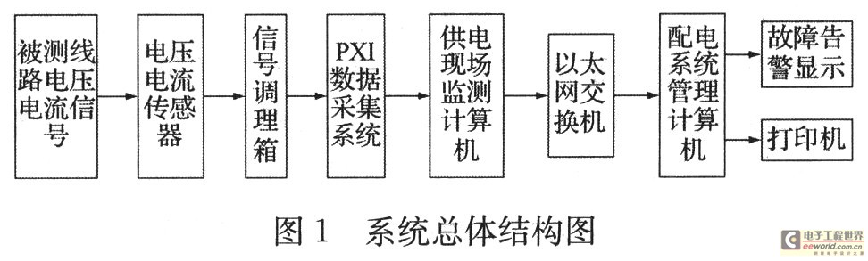
The system is used to monitor various power parameters in the power supply system circuit. According to the characteristics of the measured parameters, use the corresponding sensors to collect the voltage and current signals of the measured point through the data acquisition circuit, and then calculate the voltage, current, frequency, harmonic content, and distortion coefficient of the AC power supply system based on the collected measured point data , Crest factor and other power parameters. The monitoring system mainly includes management computer, monitoring computer, PXI data acquisition system, signal conditioning and industrial Ethernet switch and printer. The overall structure of the system is shown in Figure 1.
2 System hardware design
The management computer is mainly used for the system's running status and data management, coordinating the system's operation, providing users with real-time on-site monitoring, and realizing unified monitoring and data management. The on-site monitoring computer mainly completes the signal monitoring of the measured point of the power supply system for data collection and data analysis; the PXI data collection system mainly realizes the real-time data acquisition of voltage and current from the measured line. According to the monitoring requirements of the site under test, two PXI data acquisition cards PXI-6254 from NI Corporation are selected. Each board has 32 analog input channels and a total of 64 analog input channels. The power supply on-site monitoring computer can analyze the data collected by the PXI data collection system and generate a report to upload to the power distribution system management computer according to the user's needs through the Ethernet switch; the power distribution system management computer has a fault alarm function, which can also be transmitted via Ethernet The network accepts the data from the field computer for data analysis, replays the monitoring fault signal, and finds the cause to solve the problem.
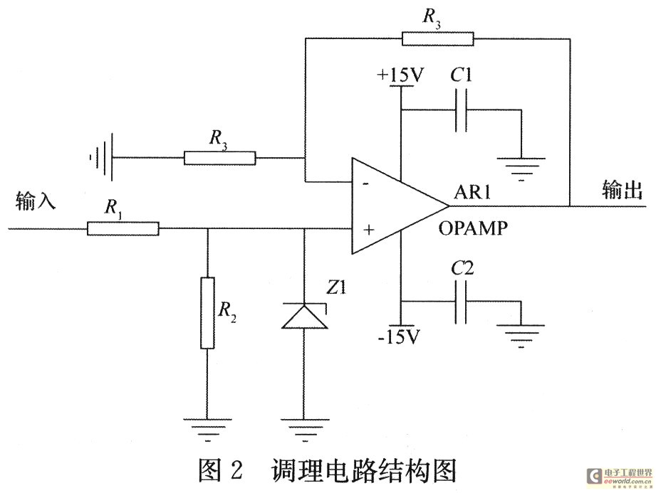
The data acquisition module is mainly composed of signal conditioning circuit, hardware synchronization circuit, A / D conversion circuit and so on. The signal conditioning circuit mainly completes the function of conditioning the voltage and current signals of the measured point to the range that the acquisition card can bear. The conditioning circuit is mainly composed of voltage transformers, current transformers, op amp circuits, follower circuits, etc., which realizes the electrical isolation of external power high voltage and high current signals from this system, reduces external electromagnetic interference, improves electrical safety performance and Reliability, and linear transformation of the input signal, signal conditioning circuit shown in Figure 2. Current conditioning uses a precision resistor to convert the current signal into a voltage signal, and then sends it to the input of the conditioning circuit. Finally, the software module in the system is used to collect data from the conditioned signal.
3 System software design
3.1 Introduction of LabVIEW software
In this test system, NI's LabVIEW7.1 is used to develop system monitoring application software. LabVIEW is an efficient graphical application development environment. It combines simple and easy-to-use graphical development methods with the advantages of a flexible and powerful programming language. It is easy to achieve seamless connection between software and hardware. After completing data acquisition, you can take advantage of the powerful LabVIEW The data analysis module completes data processing and display, and can efficiently create stable software codes. On the basis of the previous stand-alone test, it has been re-developed, developed some special processing modules, and successfully used LabVIEW network communication technology to enable the management computer and test computer to exchange network data.
3.2 Software design of monitoring system
In order to save memory resources, in addition to using DataSocket technology to share and publish real-time data, the system status monitoring software also uses Lab-VIEW's unique VI Server technology, and uses the library function programming provided by it to achieve dynamic control of the program, ensuring that the VI is It is loaded into memory only when needed, reducing system memory usage and improving operating efficiency.
The monitoring system application software is divided into management computer application software and on-site monitoring computer application software. Management computer application software, running on the management computer, mainly completes the coordination management function of the power supply system, and can achieve fault alarm and other functions; on-site monitoring computer application software, running on the on-site monitoring computer, can complete real-time monitoring, data storage, Functions such as historical playback, report generation and data information upload.
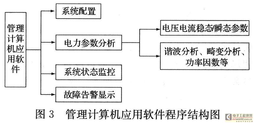
The management computer application software is mainly composed of four modules. The program structure is shown in Figure 3. The function of the system configuration module is to realize the setting of RS485 bus communication parameters and Ethernet parameters, etc .; the power parameter analysis module is mainly used to retrieve the relevant data collected by the on-site monitoring computer through Ethernet when the on-site monitoring computer fails to alarm Perform analysis, and then perform fault diagnosis based on the analysis results to eliminate system faults and ensure power supply; the system status monitoring module is mainly used to display the operating status of the monitoring system.
The on-site monitoring computer application software consists of four main modules: data acquisition module, data analysis module, fault alarm module and local waveform monitoring module. In order to realize the monitoring of the monitoring lines in the power supply system, the on-site monitoring computer must first collect the signals of the monitored lines through the data acquisition module, and can use the data analysis module to analyze, such as the analysis of voltage and current steady state / transient parameters , And can realize harmonic analysis, distortion analysis and power factor analysis of the power grid, and then automatically determine whether there is a fault based on the analysis results. If there is a fault, the fault information is uploaded to the management computer through the fault alarm module, and the relevant data is saved at the same time ; If there is no fault, give up saving this part of data. For the convenience of monitoring, the software can also record data first, and then perform characteristic parameter analysis, or directly enter a single module to directly analyze the parameters. The local waveform monitoring module synchronously collects waveforms of multiple channels in real time, and can send the site monitoring results to the management computer through the network for users to monitor at the remote terminal. The data acquisition module, data analysis module and local waveform monitoring module all contain functions such as data storage, playback, report generation and printing. The on-site monitoring computer program flow is shown in Figure 4.

4 Application of remote communication technology in monitoring system
The remote monitoring of the power supply system is mainly achieved by using network communication technology. Remote panel and DataSocket communication is a data communication method developed by LabVIEW to adapt to the development of industrial Ethernet. The remote panel supports direct operation of the VI front panel located on the remote computer, and DataSocket can be used to publish test data at high speed and in real time.
1) Remote panel technology
In order to realize real-time monitoring of the status in the remote site, the system uses remote panel technology. When performing remote monitoring, LabVIEW's remote panel technology can enable users to monitor the situation on the site through the network in the office computer. Remote panel technology realizes remote monitoring of power supply system by setting relevant parameters in LabVIEW. This technology allows users to open and operate the front panel of the VI located on the remote computer directly on the client.
2) DataSocket technology
With the continuous development of modern science and technology, using Web Server to spread VI dynamic images on the network can achieve satisfactory results. Lab-VIEW provides a method for real-time high-speed data exchange on the Internet-DataSocker, which is mainly oriented to measurement and online real-time high-speed data exchange, can be used for data exchange between multiple applications in a computer or network, thus Meet the needs of remote on-site monitoring.
5 Conclusion
The network-based power quality monitoring system proposed in this paper can not only complete the electrical parameter testing of the power supply system, but also enable users to monitor and control the scene on the remote terminal. It is found through experiments that the monitoring system has the characteristics of stable operation, high measurement accuracy, good real-time performance, simple operation, and easy maintenance. The system can meet the requirements of remote monitoring and control of the power supply system.
52V 75W/120W POE Switch Power supply for POE injector, high voltage 52 volt 75W/120W power supply
52V 75/ 120W power supply
For POE injector, POE Switch, to power IP camera, IP phone, Access point, powered over ethernet.
Features:
Input voltage range: AC 110V ~ 240V 47-63Hz
Rated output rating: Load regulation: 3-48v±5% 48W Max.
Output no-load voltage: 105% output voltage Max(Nom.)
Inrush current (Cold): 80A Max.
Protection: OCP/ OVP/ SCP
Dielectric strength: Input – Output 3.0 KV for 1 minute
Insulation resistance: 500VDC 50MΩ Mini
Efficiency: 90% Normally @ rated load
Ripple & Noise: 1% output voltage Max.
Line regulation: ±1%
Hold up time: 3ms
Temperature rise: 95 °C Max. @ rated load / Class B
IP Camera, IP phone, WIFI Access Point 802.3 af/at
POE Switch,POE Switches Puzzle,POE Switches 4 Port,POE Switches For Sale
Guangdong Steady Technology Co.LTD , https://www.steadysmps.com