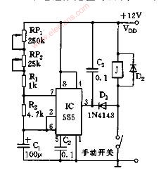
Wiper delay control circuit diagram
2 Phase 3 Wire Energy Meter Is Wired To The Inverter
2 Phase 3 Wire Energy Meter Is Wired To The Inverter,3 Wire Energy Meter Is Wired To The Inverter,2 Phase Energy Meter Is Wired To The Inverter,Wire Energy Meter Is Wired To The Inverter
TRANCHART Electrical and Machinery Co.,LTD , https://www.tranchart-electrical.com