1 background knowledge
Differential images have been widely used in many fields, such as video compression, biomedical diagnostics, astronomy, remote sensing, and face recognition.

2 matlab simulation
MATLAB source code:
Main.m
I = imread('flower.bmp'); figure, imshow(I);
I_gray = rgb2gray(I);figure,imshow(I_gray);
Id = mipcentraldiff(I_gray,'dx'); figure, imshow(Id);
Mipcentraldiff.m
Function dimg = mipcentraldiff(img,direction)
% MIPCENTRALDIFF Finite difference calculations
%
% DIMG = MIPCENTRALDIFF(IMG,DIRECTION)
%
% Calculates the central-difference for?a given direction
% IMG : input image
% DIRECTION : 'dx'?or 'dy'
% DIMG : resultant image
%
% See also MIPFORWARDDIFF MIPBACKWARDDIFF MIPSECONDDERIV
% MIPSECONDPARTIALDERIV
% Omer Demirkaya, Musa Asyali, Prasana Shaoo, ...
% Medical Image Processing Toolbox
Img = padarray(img,[1 1],'symmetric','both');
[row,col] = size(img);
Dimg = zeros(row,col);
Switch(direction)
Case'dx',
Dimg(:,2:col-1) = (img(:,3:col)-img(:,1:col-2))/2;
Case'dy',
Dimg(2:row-1,:) = (img(3:row,:)-img(1:row-2,:))/2;
Otherwise,
Disp('Direction is unknown');
End
Dimg = dimg(2:end-1,2:end-1);
Simulation results:

Figure 1 RGB original image

Figure 2 gray
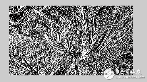
Figure 3 central_diff
3 FPGA design
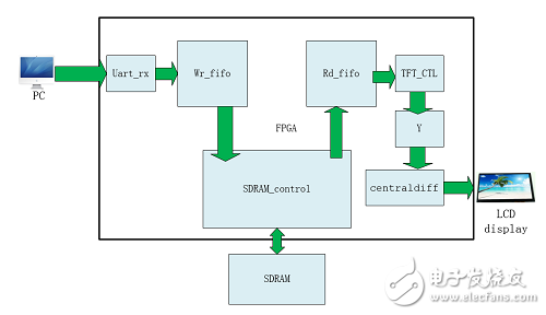
Figure 4 Center difference based on serial port transfer
As shown in Figure 4, we convert the RGB565 format to the Ycbcr format, and the Y channel enters the central differential module to complete the center difference algorithm.
FPGA source code:
*/
//////////////////////////////////////////////////////////// //////////////
Wire [15:0] rgb;
Wire hs;
Wire vs;
Wire de;
Wire o_hs;
Wire o_vs;
Wire o_de;
Wire[7 : 0]o_y_8b;
Wire[7 : 0]o_cb_8b;
Wire[7 : 0]o_cr_8b;
//assign TFT_rgb = {o_y_8b[7:3],o_y_8b[7:2],o_y_8b[7:3]}; //Y
//assign TFT_rgb = {o_cb_8b[7:3], o_cb_8b[7:2], o_cb_8b[7:3]}; //cb
//assign TFT_rgb = {o_cr_8b[7:3], o_cr_8b[7:2], o_cr_8b[7:3]}; //cr
//////////////////////////////////////////////////////////// ////////////
Tft_ctrl tft_ctrl(
.Clk9M (clk9M), / / ​​system input clock 9MHZ
.Rst_n(Rst_n), // reset input, low reset
.data_in({Rd_data[7:0], Rd_data[15:8]}), / / ​​data to be displayed
.hcount(), // TFT line scan counter
.vcount(), // TFT field scan counter
.TFT_RGB(rgb), // TFT data output
.TFT_HS(hs), // TFT line sync signal
.TFT_VS(vs), // TFT field sync signal
.TFT_CLK(TFT_clk), // TFT pixel clock
.TFT_DE(de), // TFT data enable
.TFT_begin(tft_begin),
.TFT_PWM(TFT_pwm)//TFT backlight control
);
Rgb_to_ycbcr rgb_to_ycbcr_inst(
.clk(TFT_clk),
.i_r_8b({rgb[15:11],3'b0}),
.i_g_8b({rgb[10:5], 2'b0}),
.i_b_8b({rgb[4:0],3'b0}),
.i_h_sync(hs),
.i_v_sync(vs),
.i_data_en(de),
.o_y_8b(o_y_8b),
.o_cb_8b(o_cb_8b),
.o_cr_8b(o_cr_8b),
.o_h_sync(o_hs),
.o_v_sync(o_vs),
.o_data_en(o_de)
);
Reg [7:0] diff_data;
Reg [7:0] o_y_8b_r0;
Reg [7:0] o_y_8b_r1;
Reg [7:0] o_y_8b_r2;
Reg hs0;
Reg hs1;
Reg hs2;
Reg vs0;
Reg vs1;
Reg vs2;
Reg de0;
Reg de1;
Reg de2;
Always @(posedge TFT_clk or negedge Rst_n) begin
If(!Rst_n) begin
Hs0 <= 0;
Hs1 <= 0;
Hs2 <= 0;
Vs0 <= 0;
Vs1 <= 0;
Vs2 <= 0;
De0 <= 0;
De1 <= 0;
De2 <= 0;
O_y_8b_r0 <= 0;
O_y_8b_r1 <= 0;
O_y_8b_r2 <= 0;
End
Else begin
Hs0 <= o_hs;
Hs1 <= hs0;
Hs2 <= hs1;
Vs0 <= o_vs;
Vs1 <= vs0;
Vs2 <= vs1;
De0 <= o_de;
De1 <= de0;
De2 <= de1;
O_y_8b_r0 <= o_y_8b;
O_y_8b_r1 <= o_y_8b_r0;
O_y_8b_r2 <= o_y_8b_r1;
End
End
Always @(posedge TFT_clk or negedge Rst_n) begin
If(!Rst_n)
Diff_data <= 0;
Else if(de2)
Diff_data <= (o_y_8b_r2 - o_y_8b_r0) >>1;
Else
Diff_data <= diff_data;
End
Assign TFT_rgb = {diff_data[7:3], diff_data[7:2], diff_data[7:3]};
Assign TFT_de = de1;
Assign TFT_hs = hs1;
Assign TFT_vs = vs1;
Endmodule
The results show:
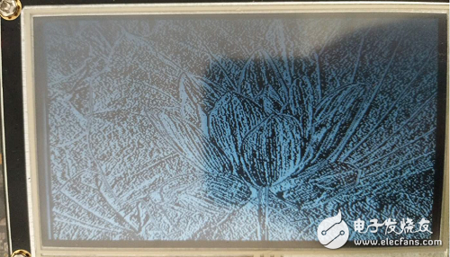
Figure 5 FPGA Center Difference Results
As shown in Figure 5, the picture is not very clear due to the reason of the mobile phone shooting, but the basic results are the same and the experiment is successful. We will port the central differential module to the ov5640-based real-time image acquisition system to complete the rgb three-channel color output.
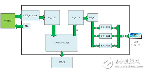
Figure 6 ov5640 based r / g / b channel color real-time output center difference
The experimental results were successful and some were colored.
ZGAR Aurora 1800 Puffs
ZGAR electronic cigarette uses high-tech R&D, food grade disposable pod device and high-quality raw material. All package designs are Original IP. Our designer team is from Hong Kong. We have very high requirements for product quality, flavors taste and packaging design. The E-liquid is imported, materials are food grade, and assembly plant is medical-grade dust-free workshops.
Our products include disposable e-cigarettes, rechargeable e-cigarettes, rechargreable disposable vape pen, and various of flavors of cigarette cartridges. From 600puffs to 5000puffs, ZGAR bar Disposable offer high-tech R&D, E-cigarette improves battery capacity, We offer various of flavors and support customization. And printing designs can be customized. We have our own professional team and competitive quotations for any OEM or ODM works.
We supply OEM rechargeable disposable vape pen,OEM disposable electronic cigarette,ODM disposable vape pen,ODM disposable electronic cigarette,OEM/ODM vape pen e-cigarette,OEM/ODM atomizer device.

Aurora 1800 Puffs,ZGAR Aurora 1800 Puffs Pod System Vape,ZGAR Aurora 1800 Puffs Pos Systems Touch Screen,ZGAR Aurora 1800 Puffs Disposable Vape Pod System,1800Puffs Pod Vape System
ZGAR INTERNATIONAL(HK)CO., LIMITED , https://www.sze-cigarette.com