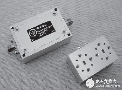
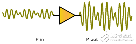
RF power amplifiers (RF PAs) play a crucial role in wireless communication systems. In the front-end of a transmitter, the RF signal generated by the modulating oscillator is typically low in power and needs to go through several stages of amplification, including buffering, intermediate amplification, and finally the power amplification stage. Only after achieving sufficient RF power can the signal be effectively radiated through an antenna. Therefore, an RF power amplifier is essential for generating the required output power.
RF amplifiers come in various types, such as high-gain amplifiers, low-noise amplifiers, and medium-to-high-power amplifiers. At the core of these circuits lies a microwave transistor, which enables efficient signal amplification at high frequencies.
RF power amplifiers operate at high frequencies but typically have a narrow bandwidth. To ensure proper performance, they often use a frequency-selective network as their load. These amplifiers are classified into three main operating modes: Class A, Class B, and Class C, based on the conduction angle of the current.
In Class A amplifiers, the current flows throughout the entire cycle (360°), making them ideal for small-signal, low-power applications. Class B amplifiers conduct for half the cycle (180°), while Class C amplifiers conduct for less than 180°, allowing for higher efficiency and power output. Among the three, Class C amplifiers offer the highest output power and efficiency. However, they introduce significant waveform distortion, so they are usually used with a resonant tuning circuit that filters out unwanted harmonics, ensuring a cleaner sinusoidal output.
The structure of an RF amplifier generally includes three key components: the input matching network, the output matching network, and the biasing circuit. Matching networks are typically designed using tools like ADS (Advanced Design System) to achieve optimal performance across a specific frequency band, which is usually narrow. After initial design, fine-tuning helps improve the overall performance.
For example, the AVAGO MGA30889 series has built-in matching circuits, simplifying the design process. All that is needed is to add DC-blocking capacitors, such as C7 and C8. Additionally, L1 and C8 form the DC biasing circuit, while C1, C2, and C3 serve as power supply filter capacitors.
DC-blocking capacitors are essential in RF amplifier designs. Their value determines the cutoff frequency of the operating band. At high frequencies, the capacitor's behavior becomes more complex due to the skin effect. The capacitor acts as a high-pass filter, and its size directly affects the high-frequency response. Common values include 100pF, 1000pF, or 0.01µF. Smaller capacitors result in a higher cutoff frequency but may cause more high-frequency loss, while larger capacitors reduce loss but lower the cutoff frequency.
The biasing inductors also play a critical role. Larger inductors lower the cutoff frequency but may degrade high-frequency performance and increase harmonic distortion. Smaller inductors allow for better high-frequency response but may not support high supply currents. Typically, inductors above 100nH are used, with the inductance chosen based on the supply current requirements. For applications requiring flat gain, tapered inductors combined with high-frequency capacitors can be used to enhance performance. A BIAS-TEE configuration is commonly employed to meet most design specifications.
General Purpose Scanners,General Purpose Barcode Scanner,Ls2208 General Purpose Barcode Scanner,Symbol Ls2208 General Purpose Barcode Scanner
Guangzhou Winson Information Technology Co., Ltd. , https://www.barcodescanner-2d.com