Abstract: With the increase of electronic control units in the car, the in-vehicle communication network has become increasingly diverse. The Automotive Electronics Association (SAE) divides the in-vehicle communication network into four categories. The Class A low-speed network is mainly used for body control such as lighting control and door window control. LIN (Local Interconnect Network) is a Class A-compliant communication standard proposed by several auto manufacturers and semiconductor companies to reduce communication costs and improve performance. LIN has a good application prospect in vehicle body control due to its low communication cost and convenient development. In this paper, the LIN bus is described in detail, and the application of the LIN bus in the body control is illustrated by taking the light control as an example.
This article refers to the address: http://
Keywords: in-vehicle communication network LIN bus body control lighting control
The Application of LIN Bus in Automotive Body Control
Abstract:With the increasing of Electronic Control Unit (ECU) in vehicle, communication networks in vehicle are in variety. The Society of Automotive Engineers (SAE) classified in-vehicle networks into four classes, in which the Class A for low-speed networks Mainly apply for body control system such as light control, doors and windows control. In order to reduce costs and enhance performance, many automotive manufactures and semiconductor companies created a new communication standard in line with Class A, that is LIN (Local Interconnect Network) LIN is a low-cost and easier development network, which will well apply for body control system. This paper describes LIN bus in detail and explains LIN bus how to apply for automotive body control by the example of light control.
1 Introduction
Due to the increase in the number of electronic control units in the car, the number of wiring harnesses in the car has increased significantly, which brings many problems: reduced layout space;
Adding difficulty to manufacturing and installation; adding additional harnesses will increase the cost of the wire harness, making it difficult to improve the price/performance ratio; a large number of wire harnesses increase the weight of the car, which is not conducive to improving fuel efficiency and performance; a large number of connection points increase the risk of failure . Therefore, it is necessary to introduce a communication network in the car to manage the increasing number of electronic devices. The automotive network can flexibly and easily integrate subsystems to achieve more complex systems, while reducing the wiring harness and weight of the vehicle, reducing the cost of the electronic control unit and increasing the reliability of the system. There are many types of in-vehicle communication networks. The Automotive Electronics Association (SAE) divides the in-vehicle communication network into four categories, as shown in the following table:
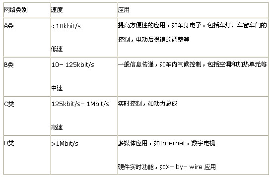
The communication between the electronic control units selects different communication networks according to the requirements of communication bandwidth and communication speed. The electronic control unit of the body control part can use the Class A low-speed communication network because the amount of data transmitted is relatively small and the real-time requirements are not high. At present, many body control solutions use CAN's low-speed network to achieve communication. Recently, many car manufacturers and semiconductor companies have jointly developed a communication standard for low-speed networks that can achieve in-vehicle comfort and convenience. The communication standard is LIN. Since LIN is based on the general-purpose SCI/UART interface, unlike CAN, which requires a dedicated controller, and LIN is a single-wire transmission, its communication cost is lower than that of CAN. Therefore, using LIN instead of the original low-speed CAN can reduce the system. Cost increases system performance.
2. LIN bus overview
The LIN bus solution was created by a number of car manufacturers and semiconductor companies to find a lower cost sub-bus network as an aid to a wide range of CAN communication networks. The LIN network is based on a master-slave architecture that uses single-wire communication to reduce the weight and cost of a large number of harnesses. The LIN target application is a low speed system that does not require CAN performance, bandwidth and complexity, such as
Switch-type load or position type systems include the control of the rear view mirror, car lock, car seat, window, etc. of the car. LIN is more conducive to the realization of distributed control systems in the car connected to the CAN network.
2.1 LIN bus features
• Low cost single-wire 12v data transmission with line drive and reception characteristics in line with the improved ISO 9141 single line standard
• Transmission rate up to 20Kbit/s
• Single master/multi-slave structure, no bus arbitration is required, and the master node controls the bus access.
• Based on a general-purpose UART/SCI hardware interface, implemented in a low-cost semiconductor process, almost all microcontrollers have the necessary hardware for LIN
• Self-synchronization can be achieved from a node without a crystal or ceramic oscillator, reducing slave hardware cost
• Ensure latency in signal transmission under worst-case conditions to avoid bus access violations.
2.2 LIN communication protocol and data frame format
A LIN network consists of one master node and multiple slave nodes. All nodes include a slave task, which is divided into sending and receiving tasks. The master node also includes a master task. All communication in the LIN network is initiated by the main task, as shown below. The main task sends a message head to all the slave tasks. The frame header consists of three parts: the synch break, the synch field, and the identifier.
The task judges whether to respond to the main task by using the information identifier, and starts to send the response information if it needs to respond to the main task. The response message consists of 2, 4 or 8 data bytes and 1 checksum byte.
The information identifier indicates the content of the information, not the destination address of the information. This definition allows multiple nodes to receive the same information, and the data can be exchanged in a variety of ways. Data can be sent from the primary node to one or more secondary nodes, or from the secondary node to the primary node or other secondary nodes. Therefore, communication between nodes does not need to go through the master node, and the master node can broadcast information to all nodes in the network. The main task in the master node controls the timing and priority of the transmission of data frames.
The master node transmits information to the slave node, and the slave node transmits information only when the master node asks. The slave node actively sends the message only when it needs to send wakeup information.
The LIN data frame consists of the frame header and response information, as shown in Figure 1. The frame header is sent by the main task. The main task sends a sync field (0x55) after the sync interval is issued. The slave node uses the sync field to adjust its baud rate to the baud rate of the transmitted signal. After that, a one-byte information identifier is sent, wherein 0 to 3 bits indicate information categories, 4 to 5 bits indicate information length, and 7 to 8 bits are parity. From the task through the byte to determine whether the data is related to itself, and determine how to handle the data. The response information is sent from the task and consists of 2, 4 or 8 byte length data and 1 byte sum check. The checksum indicates the end of the data frame, and the check is obtained by calculating all the bytes of the data (excluding the identification byte and the sync field).
Another frame of the LIN bus is the sleep frame, issued by the main task, which is used to put the bus and nodes into a low-power state. The recognition field of the sleep frame contains a value other than 0x80, except that the sleep frame is similar to the data frame. When the wake-up signal is received, the bus sleep state is aborted. The wake-up signal is sent from the task.
2.3 LIN physical interface
The physical interface of LIN is shown in the figure below. The physical interface of LIN is based on the general SCI (UART) hardware interface. The SCI (UART) interface is a silicon module integrated by almost all microprocessors, so it is more convenient to use LIN. LIN is a single-wire transmission of data, each node through the pull-up resistor line and bus, the power supply from the car power network to obtain VBAT. A diode in series with the pull-up resistor prevents the electronic control unit ECU from powering up through the bus in the event of a local battery power loss.
3. Lin body control application program
The body control system mainly includes a light control module, a door control module and a meter display module. The basic principle of these modules is to collect the state quantities of various switches according to these state quantities to drive the load action, so the control objects of the body control system are mainly different. Power lamps, low speed motors, solenoid valves and switching devices. They do not require high real-time information transmission, so the communication network of the body control system can adopt Class A standard. LIN is the open bus protocol standard for Class A automotive communication networks jointly proposed by many automobile manufacturers and semiconductor companies. At the same time, considering that the body control system is sensitive to cost, LIN has become the first choice for the body control system network with its low cost.
The figure below shows the solution for the truck body control system. The separation of these electronic control modules of the body control system from the vehicle drive system is beneficial to ensure the real-time performance of the drive system, which is also a reason for the classification of the communication network within the vehicle. The central control module of the body control system is also a gateway that connects the CAN network to the LIN network.
This paper selects the central control module and the lighting control module to illustrate the application of the LIN bus. The central control module is located in the cab of the vehicle, mainly detects the state of the control switch in the cab, and implements the corresponding control strategy according to the state of these control switches, and then sends the control commands to the sub-modules through the LIN bus, and receives them through the CAN bus. Some information about the upper CAN network. The MCU of the central control module uses Motorola's 08 series single-chip microcomputer MC68HC908GZ16, which is a high-reliability and anti-interference-capable automotive-specific chip. It integrates CAN controller and SCI module, which facilitates CAN. And the development of LIN. The CAN interface chip in the central control module uses Motorola's MC33388, and the LIN interface chip uses Motorola's MC33399. The function of the POWER unit of the central control module is to convert the 24v voltage in the car into 5v to supply the MCU. The DETECT unit functions to acquire the state of the switch and convert the parallel data into serial data for transmission to the MCU. The central control module can also add drive units according to different requirements. In this example, the central control module also completes the work of driving the interior lights and wiper motors in the car. The drive chips are selected from Motorola's MC33286 and MC33289.
The light control module has two blocks, located at the front and rear of the car, which mainly control the front and rear lights. The MCU of the lighting control module adopts Motorola's low-cost single-chip MC68HC908EY4, and the driver chip is selected according to the power required by the lamp. This paper selects several MC33288 and MC33286 of Motorola.
4 Conclusion
The application of the LIN bus in the body control system reduces the cost of the low-end communication network, increases the flexibility of the design, improves the reliability of the system, and facilitates the development of the distributed body control system. Therefore, LIN bus has a good application prospect in the automotive field. In addition, as an open protocol, LIN bus can also be used in the field of industrial and home appliances to realize communication between devices with low speed requirements and short distance connections.
references:
1 LIN Specification Package 2.0 online. LIN Consortium.2003
2 Local Interconnect Network Applications. Motorola Inc.2004
3 Local Interconnect Network (LIN) Demonstration. Motorola Inc.2000
Traditional Elliptical Sodium Lamp Reflector,250w-1000w,we can also make custom products.
Traditional Reflector,Safety Parabolic Reflector,Aluminum Parabolic Reflector,Parabolic Lampshade Reflector
Yangzhou Huadong Can Illuminations Mould Manufactory Co., Ltd. , https://www.light-reflectors.com