Abstract: The number of degrees of freedom of the single leg of the mobile platform was selected, and the range of motion of the joint was set. On this basis, using the results of single-leg kinematics analysis, the changes of the working space of the foot end when the ratio of the length of the thigh and the calf are different are studied, and the optimal proportional relationship between the two is determined. Finally, based on the cubic B-spline curve, the planning of the foot-end trajectory of the swinging leg is carried out.
This article refers to the address: http://
The foot movement method relies on discrete contact points with the ground to achieve good motion performance and dynamic performance in complex terrain. Compared with the wheeled or crawler type of movement, the foot movement is more capable of adapting to complex terrain, which is why large animals are mostly quadruped mammals. The four-legged mobile platform developed by mimicking the four-legged mammal has great application potential in complex environments, and it has become a hot spot for scholars in various countries. The structural design of the leg of the four-legged mobile platform is one of the core tasks in the design process of the mobile platform. Domestic and foreign scholars have paid sufficient attention to the single-leg structure design of the mobile platform.
The leg structure of the earlier walking motorized platform is mostly modeled on the leg structure of reptiles, such as the Japanese TITAN series four-legged mobile platform. However, these walking motorized platforms are slow in movement and can achieve less gait, and the single-leg mechanical structure is the root cause of its limitation. Since the announcement of the Bigdog four-legged mobile platform, the walking structure of the leg-like mammal has been attracting attention. As a typical representative of the high-performance four-legged mobile platform, the Bigdog four-legged mobile platform is divided into four sections with four active degrees of freedom, and the foot is equipped with passive freedom to reduce leg and ground impact. Heavy-duty carrier platform after Bigdog--The LS3 four-legged mobile platform has three active degrees of freedom on one leg, the joint movement is very flexible, and the overall active compliant control eliminates the foot end spring. The Bigdog series' newest product, the four-legged mobile platform, also has three active degrees of freedom on one leg. The ability to coordinate operations is more powerful, and the joint activities are more comfortable, making it ideal for use in human living environments.
From the development of the Bigdog series four-legged mobile platform, it can be seen that the structure of the single leg has an important impact on the performance of the mobile platform, which in turn determines the application field of the mobile platform. The structural design of the single leg mainly includes the degree of freedom of the single leg, the setting of the range of motion of each driving joint, the length ratio of each leg section, and the curve of the foot end.
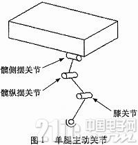
1 Single leg freedom setting and corner range of each joint
Through the study of the skeletal structure of the four-legged mammalian leg, it is found that the animal's leg is generally composed of five main parts, each part is connected by joints, and there are five active degrees of freedom in one leg. The special structure and redundant freedom of the animal's legs make it flexible and adaptable to complex terrain. The walking maneuver platform is designed to mimic the quadruped, but due to technical limitations, the single leg can not reach the active degree of freedom greater than 4. Therefore, in order to reduce the difficulty of control and reduce the complexity of the mechanical structure, the designed mobile platform has three active degrees of freedom on one leg: hip joint, hip longitudinal joint and knee joint, as shown in Figure 1. .
The body of the walking maneuver platform is continuously advanced under the push of the legs, and the range of the corners of the leg-driven joints represents the range that can be reached by the foot end of the motorized platform. The larger the range of joint angles, the larger the range of motion of the single-legged maneuver platform, and the stronger the ability of the motorized platform to move and resist lateral interference. However, the greater the range of joint motion, the greater the risk of interference in each joint segment. This problem is solved by measuring the range of joint angles of the quadruped. Jaegger et al. measured the changes in the corners of the joints of the German Shepherd (except the hip hem joint) more accurately, as shown in Figure 2.
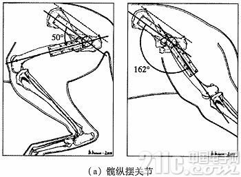
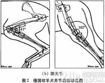
From the above figure, the range of motion of the joint angles of the German Shepherd can be obtained, as shown in Table 1.
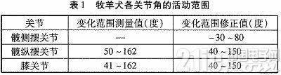
From the data in Table 1, it can be obtained that the range of motion of the joint of the shepherd dog is substantially around 110°. In the design process of the walking maneuver platform, considering the performance of the mechanical system, the performance of the animal skeletal muscle system cannot be achieved, and when the same type of hydraulic cylinder is used for each driving joint, the overall complexity of the mobile platform is greatly reduced, so the table is The range of variation of the joint angles was corrected, and the corrected range of joint motion was used as the range of motion of the joints of the motorized platform.
2 Single leg kinematics analysis
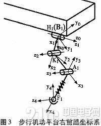
The kinematics analysis of the single leg of the walking maneuver platform is the basis for the follow-up work of the dynamic solution of the mobile platform and the rational planning of the foot curve. In this paper, the kinematics analysis of the single leg of the mobile platform is carried out by D-H coordinate method (taking the right front leg as an example).
First, the D-H coordinate system of each leg segment is established, as shown in FIG. B1-x0y0z0 is the right front leg coordinate system, H1-x1y1z1 is the hip joint longitudinal joint coordinate system, K1x2y2z2 is the hip longitudinal joint coordinate system, A1-x3y3z3 is the knee joint coordinate system, and F1-x4y4z4 is the foot end coordinate system.
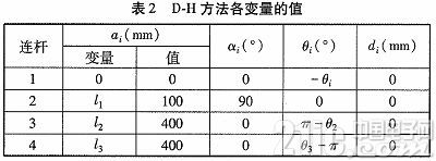
From the definition of the DH coordinate system and the size parameters of each member, the values ​​of the variables of the D-H method can be obtained, as shown in Table 2. Αi is the distance from the intersection of the zi-1 axis and the xi axis to the origin of the i-th coordinate system along the xi-axis direction; αi is the angle rotated by the xi-axis from the zi-1 axis to the zi-axis by the right-hand rule; di is the edge The distance of the zi-1 axis from the origin of the i-1th coordinate system to the intersection of the zi-1 axis and the xi axis; θi is the angle rotated by the xi-1 axis from the xi-1 axis to the xi axis by the right-hand rule .
Therefore, the rotation transformation matrix from the right front leg coordinate system to the foot end coordinate system is:
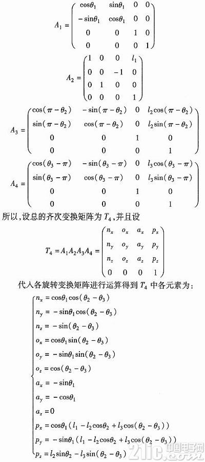
From the forward kinematics analysis, the coordinates and attitude of the foot end point in the one-leg coordinate system are obtained. The results of the positive kinematics analysis are used to study the proportional relationship of each joint segment.
3 Study on the length ratio of each leg
3.1 Robot foot end workspace analysis
The foot end working space of the walking maneuver platform is the range of spatial points that can be reached by the reference point of the swing leg end. This range represents the position that the swinging leg of the mobile platform can reach, and is an important aspect to be considered in the optimal design of the mobile platform structure. There are many methods for solving the working space of the foot end, such as analytical method, graphic method or numerical method. Using the results of the forward kinematics analysis, the working space cloud map of the foot end point of each active joint angle is obtained in Matlab, and then the image processing method is used to solve the working space area of ​​the foot end. The steps to solve are:
1) Within the range of variation of each joint, the joints are sequentially produced with a certain rotation angle, and a combination of joint angle variables is obtained.
2) Bring the joint angle variable into the positive kinematics solution, obtain the coordinate values ​​of a set of foot end points, and make a graph of the same, and combine the numerous graphs to form a cloud map.
3) According to the image processing method in Matlab, the area of ​​the foot end space is obtained.
3.2 Study on the length ratio of each leg segment
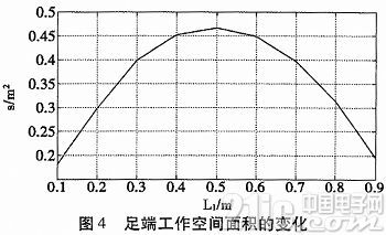
Since the walking maneuver platform is mainly moving in the front-rear direction, the lateral movement is often used to ensure the stability of the maneuvering platform itself, and the ability of the maneuver platform to adapt to the complex terrain is stronger, and the two pendulum joint segments are the movement of the body in the front-rear direction. The rod, therefore only the length ratio of the two longitudinal joint segments is studied. In order to make the study simple and representative, it is assumed that the total length of the hip longitudinal section and the lower leg section is 1 m, and the lengths of the two leg sections are sequentially 0.1 to 0.9 m, the step length is 0.1 m, and L1 is the hip joint longitudinal pendulum. Segment length identification, L2 is the length identification of the calf segment. When L1 and L2 take different proportions, use Matlab to make a cloud map of the workspace and calculate the area size, as shown in Table 2.
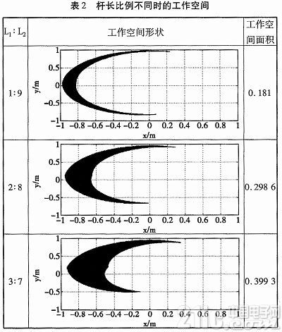
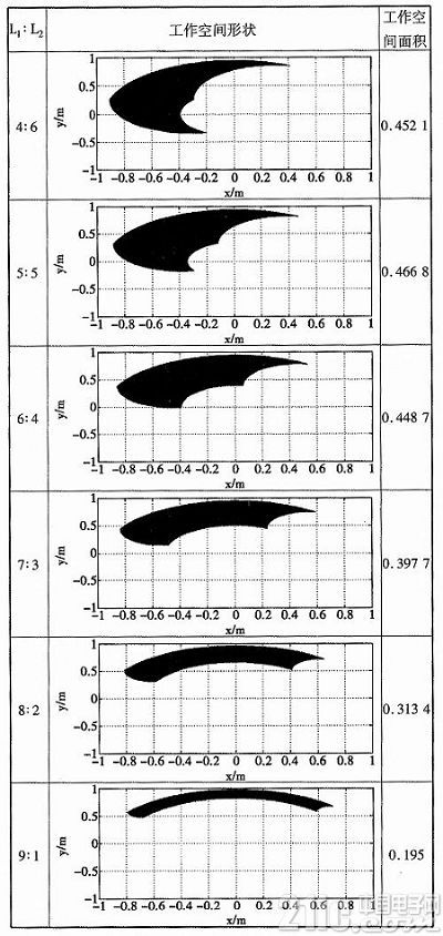
It can be obtained from Table 2 that with the increase of the ratio of L1 and L2, the size of the working space on the foot of the mobile maneuver platform changes significantly, and the reachable range of the foot end increases first and then decreases, so there is an optimal maximum for the working space of the foot end. proportion. For the sake of comparison, a graph of the size of the working space of the foot end and the length L1 of the longitudinal section of the hip is made. It can be more intuitive from Fig. 4 that when L1 and L2 are equal, the working space area of ​​the foot end is the largest.
4 Foot trajectory planning
The foot-end trajectory planning of the walking maneuver platform is an important aspect of the one-leg design of the mobile platform. The foot end trajectory planning is generally designed to move the foot end of the walking maneuver platform relative to the ground coordinate system. Since the hip sway joint does not generally function during the normal walking of the maneuvering platform, the foot trajectory planning is performed in the single leg plane of the maneuvering platform. The walking maneuver platform realizes its obstacle crossing and advancing functions through the legs, and the foot foot trajectory planning is mainly the trajectory planning of the swinging leg foot end. The trajectory planning of the swinging leg foot end directly determines the obstacle-obstructing ability and athletic ability of the mobile platform. Commonly used foot end trajectories include parabola, straight line segments, and cycloidal lines. In this paper, the three-B-spline curve is used to plan the foot end of the mobile platform.
4.1 Concept of cubic B-spline curve
For a given m+n+1 spatial vertex pi(i=0,1,...,m+n), the kth (K=0,1,2...n) segment n-time B-spline curve is defined as:
As a free curve, the cubic uniform B-spline curve has many good features, making it suitable as a foot-end trajectory curve when the walking maneuver platform is over obstacle. First, the cubic uniform B-spline curve has nothing to do with the absolute position of the spatial vertices, only their relative positions. Secondly, the cubic uniform B-spline curve has convex hull and convexity. By selecting the appropriate spatial vertices, the constructed foot-end trajectory curve will not produce singular points. Then, the cubic uniform B-spline curve has local modifications. Changing individual spatial vertices only affects the construction curve associated with this vertex and does not affect the overall.
4.2 Planning of the foot end trajectory
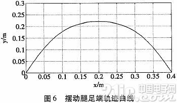
The foot-end trajectory curve of a four-legged mobile platform on a flat ground is generally described by two parameters, one is the step size s and the other is the step height h. The step size s and the step height h can better reflect the motion characteristics of the foot end trajectory curve. The greater the ratio of the general step height h to the step size s, the stronger the ability of the four-legged mobile platform to overcome obstacles, but the slower the movement speed. The smaller the ratio of step height h to step size s, the better the forward characteristics of the four-legged mobile platform, but the ability to cross obstacles is poor. For the cubic B-spline curve, in the case where the step size is constant, the step height is determined by the starting angle and the falling step angle, so the starting angle α, the falling step angle β and the step length S are introduced to describe the cubic B-spline curve. As shown in Fig. 5, α is the starting angle, β is the falling angle, p1 is the starting point, p2 is the falling point, and M is the intersection of the kicking direction and the falling direction.
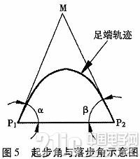
In this step S is set to 400 mm, the starting angle and the falling step angle are both 62.5 degrees, and the maximum step height is 220 mm. Therefore, the curve of the foot end of the swing leg can be obtained as shown in FIG. 6.
5 Conclusion
1) The number of degrees of freedom of the single leg of the four-legged mobile platform is set, and the range of the angle of each driving joint is set to 40°-140° on the basis of bionics analysis;
2) The kinematics analysis of the single leg was carried out, and on this basis, the working space of the foot end when the length ratio of the hip longitudinal joint and the thigh segment were different was studied, and it was found that the foot end worked when the lengths of the two were equal. The largest conclusion of space;
3) The concept of cubic B-spline curve is expounded, and on this basis, the foot-end trajectory curve is planned.
Split Type Solar Street Lights
Split Type Solar Street Lights,Solar Street Light With Pole,Solar Street Light With Camera,Waterproof Solar Street Lighting
Jiangsu Bosiwei Optoelectronics Group Co.,ltd , https://www.bswledled.com