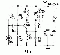
Mono FM transmitter circuit 
The picture above is the classic 1.5km single tube FM transmitter circuit. The key component in the circuit is the transmitting transistor, mostly using D40, D5O, 2N3866 and so on. The working current is 60--80mA. However, the above transistors are difficult to purchase, and the prices are higher and there are more fakes. The author chooses other transistor experiments. The relatively easy-to-purchase transistors C2053 and C1970 are quite good. The actual line-of-sight communication distance is greater than 1.5km. The author has also replaced the D40 tube with an ordinary triode 8050, and the working current is 60-80mA, but the transmission distance is less than 1.5km. If it is changed to 9018, the working current is smaller and the transmission distance is shorter. In addition to the transmitter transistor; the parameter selection of the coil L1 and capacitor C3 is more important, if not selected improperly, it will not vibrate or the operating frequency will exceed the range of 88-108MHz. Among them, L1, L2 can use 0.31mm enameled wire on a round bar of about 3.5mm to wind 5 turns and 10 turns in a single layer, and C3 uses 5-20pF porcelain or polyester adjustable capacitor. In actual production, the capacitor C5 can be omitted, and the L2 can also be replaced with a common inductance coil of 10-100mH. If the launch distance is only a few tens of meters, then the battery voltage can be selected as 1.5-3V, and the D40 tube can be replaced with a cheap 9018, etc., which will consume less power. You can also refer to the "Electronic News" 2000 No. 8 The fifth edition (simple long-range wireless FM microphone) was slightly modified after the article. The single-tube transmitter introduced in Figure 1 has the characteristics of simple circuit, large output power, and easy production, but it is inconvenient to connect the high-frequency cable to send the RF signal to the outdoor transmitting antenna. Generally, the 0.7-0.9m rod The antenna is directly connected to the C5 for transmission. Due to the Doppler effect, the frequency drift phenomenon is very serious when people move near the antenna, which makes the normal receiver sound distorted or silent. If you use this transmitter as a wireless microphone, you can imagine how serious the frequency drift is when you pinch the antenna.
Fiber Patch Cord is a length of optical cable with connectors fixed on two ends to realize the optical path active connection.If both sides of the connector or its end-face are different, it is called hybrid Fiber Optic Patch Cables.Main types of Optical Patch Cord are SC Patch Cord , LC Patch Cord , FC Patch Cord , ST Patch Cord , Multimode Fiber Patch Cord,Single Mode Fiber Patch Cord, Duplex Patch Cord , Simplex Patch Cord . In order to assure of high performance,they are made with CCTC brand`s premium grade connectors.Meanwhile,Fiber Optic Patch Cord is also available with different colors,diameter and jacket types, which can be made to any length to fit FTTH projects. Fiber Patch Cables are not only widely used for communication rooms,FTTH,LAN,fiber communication systems,fiber optic transmission equipment and other telecom fields,but also they are applicable to cable television networks, telecommunications networks, computer optical network and optical test equipment. Foclink,a reliable supplier of fiber patch cord is always beside u 7*24.
Fiber Patch Cord
Fiber Optic Patch Cord,Optical Patch Cord,Fiber Patch Cables,Fiber Optic Patch Cables
Foclink Co., Ltd , https://www.scfiberpigtail.com