MAX3740 / MAX3795 Laser Driver Average Power Monitor
The MAX3740 and MAX3795 laser drivers provide laser diode average optical power monitoring output voltage. The monitor output comes from the monitor diode current of the laser module. The laser driver of data communication equipment usually needs to monitor the average optical power. The working characteristics of the MAX3740 and MAX3795 in this respect are different from the methods used by other laser drivers. This may cause confusion when performing SFF 8472 digital diagnosis.
The monitor diode current of the laser module is approximately proportional to the average optical output power of the laser. Laser drivers generally use monitor diodes to adjust the average transmit power of laser diodes (Figures 1 and 2). This function of the driver is called automatic power control (APC).
The laser driver used in the SFP module provides a current output through an output pin of the device (Figure 1), which is the mirror current of the monitor diode. By placing a resistor on the pin, the controller (such as the DS1856) can detect a voltage proportional to the monitor diode current, which is proportional to the average power. The controller provides appropriate scaling and offset to meet the requirements of SFF 8472. The MAX3740 and MAX3795 use the voltage output PWRMON pin (Figure 2) to indicate the average power instead of using a current mirror output. The difference between these devices is that no matter how large the monitor diode current is, as long as the laser driver's automatic power control loop works normally, the PWRMON voltage will always be maintained at 0.4V. So, how does the controller use the monitor output to monitor the average optical power?
We explain this characteristic through two optical modules. Each module is set to an average power of -4dBm. For module 1, the corresponding 100μA monitor diode current, module 2 corresponds to the 200μA monitor diode current (the average optical power is the same, but the monitor diode current is different, this situation is more common, this is due to the coupling between the laser and the monitor diode Different).
For these two modules, the indicated voltage of PWRMON is 0.4V, because the APC loop adjusts the output to this voltage. The only difference between the two modules is their setting resistance.
The setting resistance of module 1 is about 2kΩ (0.2V / RPWRSET), and the setting resistance of module 2 is about 1kΩ (0.2V / RPWRSET). If for some reason, the module supplier needs to know and store the actual monitor diode current, as long as it is simple to know the setting resistance and calculate it according to the above formula. However, the value indicated on the internal calibration I2C bus that meets the requirements of SFF 8472 is the optical power output, not the MD current.
If all parts are working properly and no faults have occurred, the PWRMON voltage will remain at 0.4V. Regardless of the monitor diode current set point, the voltage is always maintained at 0.4V, and the offset is the same, as long as each module is calibrated at the same average power, the calibration can be applied to each module, thereby simplifying the internal calibration process .
If the APC exceeds the adjustment range, the voltage will change as the MD current changes. This is because all channels of MD current are high impedance except for setting resistance. Therefore, if the power is doubled, the current is also doubled, and as R is fixed, the voltage is doubled.
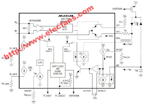

Figure 2: MAX3795 monitor structure diagram
The device fault threshold is set to 0.8V. If the MD current reaches twice the initial set point, a fault alarm will be issued. If it is at the middle point, no fault alarm will be generated. When PWRMON increases the same voltage corresponding to the MD current, the power value can be calculated.
Therefore, when the power of the above two modules is -4 dBm, the monitor diode current of module 1 is 100 μA, and the PWRMON output indicator is 0.4 V. If the loop exceeds the adjustment range due to malfunction or other reasons, the power will increase to -1dBm, and the PWRMON voltage will reach 0.8V relative to the 200μA monitor diode current. For 150μA, the voltage will reach 0.6V.
When the average power of module 2 is -4dBm, the PWRMON voltage is 0.4V, and the monitor diode current will reach 200μA. Similarly, if the loop exceeds the adjustment range, the power is increased to -1dBm, the PWRMON voltage is 0.8V, the monitor diode current will reach 400μA (the same proportion, the monitor diode current doubles, the voltage also doubles).
Compared with traditional methods, the method of monitoring the average power has other advantages. In the laser driver, the MD current mirror generates a voltage on a fixed resistor. For different modules, because each part of the monitoring diode current is different, the fault threshold may be too high or too low.
Returning to the original example, the traditional current monitoring method is used to monitor the average power of devices such as MAX3735A (Figure 1). When we set module 1 and module 2 to an average power of -4dBm, the MD current is 100μA and 200μA, respectively. The fault threshold in this case is set by the driver to a fixed value of approximately 1.3V.
In this example, the monitoring resistance in both cases is set to 3.25kΩ. Therefore, for the same average optical power, module 1 will indicate 100 μA x 3.25 kΩ = 0.325V, and module 2 will indicate 200 μA x 3.25 kΩ = 0.65V.
If the MD current is doubled (approximately double the average power), then the average power of module 1 will be -1dBm, the voltage reaches 200μA x 3.25kΩ = 0.65V, the average power of module 2 is: -1dBm, the voltage is: 400μA x 3.25kΩ = 1.3V. Note that in this example, although the power of both modules is doubled, only module 2 generates a fault alarm. In many cases, for a given average power, the MD current of each part of the laser is not much different. Therefore, the traditional scheme can work better. However, from the above analysis, it can be seen that if a large change occurs, an appropriate fault threshold cannot be set unless an adjustable resistor is used in the monitor and calibrated for each module. The MAX3740 and MAX3795 do not have this problem, simplifying the calibration process.
The MAX3740 and MAX3795 described in this article can provide a simple and effective method to monitor the output power of the laser diode in the SFF 8472 diagnostic module. Even if the monitoring diode components vary greatly, this method can provide a stable fault level indication.
Rechargeable Vacuum Cleaner is also a Handheld Vacuum Cleaner. Some rechargeable Vacuum Cleaner has charger base with multifunction,so we can store easier. Although it is basic configuration,it has complete accessories. So you can use in any places. Its basic configuration's battery is NI-CD(1200MAH),but if you want to change,it is allowed. You can change to NI-HI battery or battery pack. If the battery is Replaced,the unit price will change,too. So please consider clearly. Now I will show you some pictures about rechargeable vacuum cleaner.


Rechargeable Vacuum Cleaner
Rechargeable Vacuum Cleaner, Rechargeable Car Vacuum Cleaner, Cordless Rechargeable Vacuum Cleaner, Rechargeable Upright Vacuum Cleaner
Ningbo ChinaClean Household Appliances Manufacture Co., Ltd. , https://www.chinaclean-elec.com