Detailed explanation of the three major technical indicators of cable TV
The performance of a cable TV network system is usually measured by carrier-to-noise ratio (C / N), combined triple beat ratio (CTB), combined combined second beat ratio (CSO). The national broadcasting and television industry standard (GY / 7 106-1999) stipulates that the cable-to-noise ratio of the cable TV system is ≥43db, the combined three-time beat ratio ≥54db, and the combined second-time beat ratio ≥54db. What are the meanings of these three major indicators? Here I will introduce to you one by one.
1. Carrier-to-noise ratio
Definition: At the specified point of the system, the ratio of the image or sound carrier level to the noise level (denoted by db).
Noise is a general term for all interfering signals, and its presence affects the clarity of useful signals. The noise in the cable TV system is mainly thermal noise. In daily life, when we turn on the TV without inputting any signal, we will see that the screen is covered with irregular black and white dots, so-called "snowflakes". These "snowflakes" are the reflection of noise on the TV screen.
The noise of cable TV is mainly composed of thermal noise and shot noise. Thermal noise is mainly caused by the irregular thermal motion of free electrons inside the electrical conductor. The amount of noise power is related to the operating frequency, operating bandwidth, and operating temperature. The video bandwidth of China's TV system is 5.75MHZ, which is at normal temperature. The noise power generated is 2.4dbμV. Shot noise is generated by semiconductors in active devices such as amplifiers. Regardless of whether there is a signal or not, these noises always exist and have undulating characteristics. It appears as "snowflake" interference on the image, which is difficult to suppress. The clarity of the image will decrease with the increase of the noise level. In order to measure the reception quality of the CATV system, the carrier-to-noise ratio is used to describe it quantitatively. Its mathematical expression is: C / N = 10 * lg (carrier power / noise power), the unit is db.
In the CATV system, the power at the user end is the sum of the thermal noise at the front end plus the noise generated by all the series-connected amplifiers in the network. The amplifier is an active device, and its interior is composed of electronic devices such as transistors and resistors. The amplifier itself will also generate noise. The amplifier will amplify the signal while superimposing the noise on the output end. In this way, the signal-to-noise ratio of the signal at the output is bound to be lower than that at the input. To this end, we use the ratio of the input carrier-to-noise ratio and the output carrier-to-noise ratio to measure the noise index of the amplifier, defined as the noise figure, expressed by F, this coefficient is usually provided by the manufacturer.
According to the above, in a CATV cable network formed by multiple amplifiers connected in series, the input carrier-to-noise ratio of the latter amplifier is definitely lower than that of the previous amplifier. This is why in some CATV systems, The reason for ensuring the carrier-to-noise ratio index is that the higher the input level requirements of the later stage amplifier. The calculation formula of the carrier-to-noise ratio of the multi-stage amplifier of the same model in series is:
C / N = Vi-F-10lgn-2.4 (db) Vi is the input level; F is the noise figure of the amplifier; n is the number of amplifier stages connected in series; 2.4 is the thermal noise power at normal temperature.
2. Nonlinear distortion of CATV system
In the entire CATV network system, a large number of active devices are used, such as cable amplifiers, optical transceivers, etc. These active devices will produce nonlinear distortions, and the results of these nonlinear distortions will generate many new frequency components on the system , Called product. If these products fall within the broadcast channel band, it will cause interference to the images of these channels, such as image drawing, moire interference, "rain wiper" interference, "cross-image", etc., according to the way of interference to the image Non-linear distortion can be divided into two types: cross-talk modulation interference (also called intermodulation distortion) and inter-modulation interference (also called intermodulation distortion).
The so-called cross-talk modulation interference is when the CATV system simultaneously transmits two amplitude-modulated waves with different carrier frequencies, the active components of the system will cause the two radio frequency signals to interact, so that the useful signals in the TV passband are outside the passband Interference caused by the modulation of the interference signal. Its characteristics are: 1. Interference occurs only when a useful signal is received, and the interference signal disappears when the useful signal disappears. 2. When the interference signal is much larger than the useful signal, it will cause "blocking" (at this time, the TV cannot see any image). 3. The interval between the interference frequency and the signal frequency can be arbitrary. 4. Only the amplitude modulation signal will produce intermodulation interference. 5. When the amplitude of one of the two or more input signals is large enough to make the amplifier work to saturation, it may produce intermodulation interference. Therefore, the magnitude of the intermodulation interference reflects the linear ability of the amplifier to process the signal (that is, the dynamic range of the amplifier).
The so-called mutual interference or mutual modulation is caused by the beat (addition or subtraction) of more than two frequency components to generate new frequency components. These new frequency components are different from the frequency of any input signal, but when it falls on a certain Interference occurs in the middle of the frequency band of an input signal. Mutual interference appears as a moire on the image. Intermodulation interference and intermodulation interference generally occur simultaneously.
For any device with nonlinear distortion (such as an amplifier), under normal use, the relationship between its output voltage and input voltage can be approximated by
U0 = K1Ui + K2Ui2 + K3Ui3 where K2Ui2 is called the second-order term and K3Ui3 is called the cubic term.
In the above formula, U0 is the output voltage and Ui is the input voltage. Now suppose there are two signals A and B input at the same time, then the expression of the input signal: Ui = ACOSω1t + BCOSω2t
Output voltage: U0 = K1 (ACOSω1t + BCOSω2t) + k2 (ACOSω1t + BCOSω2t) 2 + K3 (ACOSω1t + BCOSω2t) 3
The first term of the above formula is the signal we need, which amplifies the input signal Ui by K1. The third term (called the third order term) K3 (ACOSω1t + BCOSω2t) 3 is expanded as follows:
= K3 (A3COS3ω1t + B3COS3ω2t + 3AB2COS2ω2tCOSω1t + 3A2BCOS2ω1tCOSω2t)
= K3 [3 / 4A3COSω1t + 3 / 4B3COSω2t
+ A3 / 4COS3ω1t + B3 / 4COS3ω2t
+ 3 / 4A2BCOS (2ω1 ± ω2) t + 3 / 4AB2COS (2ω2 ± ω1) t
+ 3 / 2AB2COSω1t + 3 / 2A2BCOSω2t]
In the above formula, the term containing COS3ω1t and COS3ω2t is the third harmonic term, which is called the third harmonic product. The terms containing (2ω1 ± ω2) and (2ω2 ± ω1) are beating terms, which are called cubic beating products. These terms are likely to fall into the normal channel to form intermodulation interference, so we call the part of the product where the frequency components generated by these harmonic terms and beat terms fall into the normal channel into the third order Intermodulation products, the sum of these three products is called combined triple beat, or CTB for short.
The frequency of the last two items in the formula is still the basic frequency, not the newly generated frequency, so it is not intermodulation, but their amplitude not only has the TV signal of this channel, but also the TV signal of other channels. For example, the K3 * 3 / 2AB2COSω1t item is the basic frequency ω1 of the A channel, so you will definitely receive the product of this item when watching the A channel. However, there is a B2 term in its amplitude, so a B-channel signal appears, causing a crosstalk phenomenon in which two images appear on the screen at the same time. So these two items are crosstalk modulation interference items.
The distribution of CTB products is such that most of the CTB products that fall into the working channel are generally clustered on a certain two specific frequencies, and tens, hundreds or even thousands can be clustered on these two frequencies Distortion products. This particular frequency is called the main cluster point frequency of CTB. In the adjacent equally spaced channels (such as DS6-DS12, Z1-Z37), the image carrier frequency is the main cluster point frequency of the CTB products of these channels. The number of CTBs clustered on the image carrier frequency is the middle channel. The increase or decrease of the channel is gradually reduced, showing symmetry or near symmetry.
In DS1-DS3, DS4, and DS5, the number of CTBs is relatively small, and the distribution is relatively scattered. In DS13-DS22 (550MHZ system), the main part of CTB products is concentrated in the image carrier frequency and + 1MHZ, these two frequencies are the main cluster frequency of CTB. As the channel increases, the number of CTB products on the image carrier frequency increases first and then decreases, with the most in the middle and the two ends decreasing symmetrically. At + 1MHZ, it gradually decreases.
Second-order term: K2 (ACOSω1t + BCOSω2t) 2 Expand this expression
= K2 [A2 / 2 + B2 / 2 + A2 / 2COS2ω1t + B2 / 2COS2ω2t + ABCOS (ω1 ± ω2) t]
In the formula, A2 / 2 and B2 / 2 are DC terms (low-frequency terms), which can be filtered by capacitors. The third and fourth terms are second harmonic terms (called second harmonic products), and the fifth and sixth terms It is a beating item (called a beating product). In general, the last four items are newly generated frequency items. As long as they fall within the normal channel, they will form intermodulation interference. We call these frequency components second-order intermodulation products, and the sum of these three products is generally called combined second-order distortion, or CSO for short.
In the 550MHZ system, the distribution of CSO is: only 49.5% of CSO products fall in each working channel of the system, which is much less than CTB. In the adjacent equally spaced channels (DS6-DS12, Z1-Z37), CSO is mainly distributed at -0.25MHZ and + 0.25MHZ away from the image carrier frequency; in DS1-DS3, the total number of CSO per channel is less , And most of them are distributed on the frequency far away from the image carrier frequency. In the two channels DS4 and DS5, + 2.75MHZ is the cluster point with the largest number of CSO distribution in the entire system. In DS13-DS22, CSOs are fairly concentrated at + 1.25MHZ, and the number increases with the increase of the channel.
Now the push-pull amplifier is used in the cable TV system, which greatly reduces the second-order distortion, and people's attention is focused on the CTB.
In summary, intermodulation is generated by third-order distortion CTB, and intermodulation can be generated by both second-order CSO and third-order CTB distortion. In order to quantitatively analyze the influence of these distortions on the system, two parameters of combined triple beat ratio C / CTB and combined second beat ratio C / CSO are introduced.
â‘ Combined triple beat ratio: it is the ratio of carrier level and CTB level
C / CTB = 20lg (carrier level / CTB level) The unit is: db
The CATV cable network C / CTB is related to the selection of the amplifier, the output level of the amplifier, the number of amplifier series and the number of working channels.
In CATV cable networks, each amplifier must produce CTB distortion. As the signal goes back
Progressive transmission (that is, the number of amplifiers in cascade increases) CTB will gradually accumulate, and C / CTB will gradually deteriorate. It has a relationship with the amplifier series n of 20lgn, that is, if there are n series connected amplifiers, then C / CTB indicator will drop by 20lgn (db).
The relationship between C / CTB and the number of channels transmitted is 20lg (M / m), M is the maximum number of channels transmitted by the system, and m is the number of channels actually working. That is, the smaller the number of transmitted channels, the higher the C / CTB index.
The relationship between C / CTB and the output level of the amplifier is that if the output level of the amplifier (level per channel) is reduced by 1db, the C / CTB index will be improved by 2db.
In habit, we often say CTB refers to C / CTB index.
â‘¡ Combined secondary beat ratio: it is the ratio of carrier level to CSO level
C / CSO = 20lg (carrier level / CSO level) unit is: db
The characteristics of C / CSO in CATV cable transmission network are the same as C / CTB. The relationship between the C / CSO and the output level of the amplifier is: the level of each channel increases by 1db, and the C / CSO index will deteriorate by 1db.
The relationship between C / CSO and amplifier serial connection number n is 10lgn (db).
The relationship between C / CSO and the number of transmitted channels is 10lg (M / m) (where M is the maximum number of channels transmitted by the system and m is the number of actually transmitted channels), that is, the fewer the number of channels transmitted, the more C / CSO index high. In habit, we often say CSO refers to C / CSO indicator.
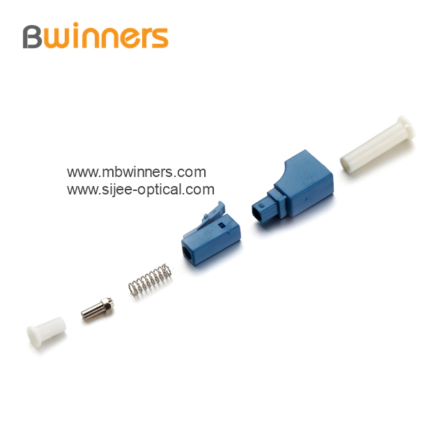
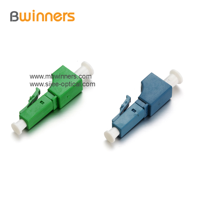
Sijee Fiber optic adaptors are part of passive components for FTTH ODN connectivity, Sijee Fiber optic adaptors are used to join two fiber optic patch cables together for realizing the transition between different interfaces and they are available for use with either single-mode or multimode Fiber Optic Patch Cord. Sijee Fiber optic adaptors can offer superior low loss performance with very high repeatability.
Sijee offers different types of fiber adaptors comply with ITU standard, main products including Fiber Mating Sleeve Adaptor, Fiber Hybrid Adaptor, Fiber Bare Fiber Adaptor , Fiber Mechanical Attenuator, Field Assembly Optical Connector (FAOC), Splice-On Connector, Semi-finished Fiber Connector, etc.
Optical Fiber Couplers,Optical Fiber Adapter,Fiber Optic Adapter, Fiber Optic Flange are available.
Features:
1. Compliant with: IEC, JIS, Telcordia
2. Convenience and ease of handling
3. Optical performance 100% factory tested
4. Flange or threaded mounting type
5. Ceramic/Zirconia or phosphorous bronze sleeves
6. Good changeability and repeatability
Applications:
1. Telecommunication networks
2. FTTX, FTTH
3. LAN, WAN, CATV networks
4. Fiber communications, Data communication networks and processing, Industrial, Mechanical and Military.
5. Active device termination


Fiber Adaptor
Optical Fiber Couplers,Optical Fiber Adapter,Fiber Optic Adapter,Fiber Optic Flange
Sijee Optical Communication Technology Co.,Ltd , https://www.sijee-optical.com