Today, I will introduce a national invention authorized patent-an STS split type electric energy meter based on low-power carrier communication mode. The patent was applied for by Jiangsu Linyang Energy Co., Ltd., and the authorization was announced on February 22, 2017.
Content descriptionThe invention belongs to the field of smart grid communication, in particular to an STS split type electric energy meter based on a low-power carrier communication mode.
Background of the inventionAt present, the concentrator carrier module is connected to the live wire/zero wire input (relay input terminal) to read the main meter, and the indoor unit carrier module is connected to the live wire input (relay input terminal) to communicate with the main meter. In this way, regardless of whether the relay is on or off, the indoor unit is always powered, and there is a risk of power theft, and separate wiring is required. The other is that the concentrator carrier module is connected to the live wire/zero wire input (relay input terminal) to read the main meter, and the indoor unit carrier module is connected to the live wire output (relay output terminal) to communicate with the main meter. When the owed fee is set, the indoor unit uses battery power to communicate with the main meter through the carrier wave. In this scheme, it lacks efficient power management and dynamic adjustment of the carrier transmission power function. There are large static leakage current, large dynamic power consumption, and battery. Short life, frequent replacement and other shortcomings.
Summary of the inventionThe purpose of the present invention is to solve the above problems and propose a STS split type electric energy meter based on low power consumption carrier communication mode.
The technical scheme of the present invention is: an STS split type electric energy meter based on low-power carrier communication mode, which includes a concentrator, a main meter and an indoor unit; the concentrator includes a main controller 1 and peripheral modules connected to it 1. Carrier module one, the two ends of the carrier module one are respectively connected to the live wire inlet and the neutral wire inlet, and the coupling capacitor C1 is connected between the carrier module 1 and the live wire inlet, and the live wire The input terminal is the relay input terminal of the main meter, and the concentrator uses the coupling capacitor C1 to connect to the live wire input terminal to read the main meter.
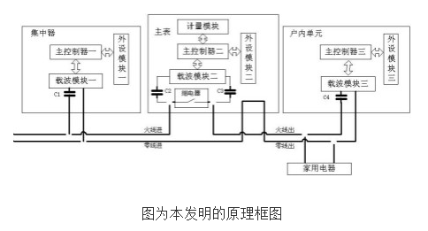
The main meter includes the second main controller and the metering module, the second peripheral module, and the second carrier module connected with it. The two ends of the second carrier module are respectively connected in series with carrier capacitors C2 and C3 and then connected to both ends of the relay. The two ends of the relay are respectively connected to the live wire inlet and the live wire outlet to measure the power consumption of the household appliance. The two ends of the household appliance are respectively connected to the live wire and the neutral wire outlet.
The indoor unit includes the main controller 3 and the peripheral module 3 and the carrier module 3 connected with it. The two ends of the carrier module 3 are respectively connected to the live wire outlet and the neutral wire outlet, and the carrier module 3 is connected to the live wire A coupling capacitor C4 is connected between the outlet terminals, and the live wire outlet terminal is the relay output terminal of the main meter. The carrier module 3 communicates with the main meter through the coupling capacitor C4 to the live wire output terminal to conduct electricity purchase and power inquiries.
The coupling capacitor C1 of the present invention is 220 nF, the coupling capacitor C2 is 220 nF, the coupling capacitor C3 is 100 nF, and the coupling capacitor C4 is 100 nF.
In the indoor unit of the present invention, the third peripheral module includes a keyboard, a power management module, a battery, a backlight circuit, an LCD display, a buzzer, and a storage module; the keyboard is an input device for users, and its signal output terminal Connected to the corresponding signal input end of the main controller three; the input end of the power management module is used as the electrical signal acquisition end to connect to the live wire and neutral wire outlet end of the electric energy meter, and the output end of the power management module is connected to the corresponding main controller three The signal input terminal; the battery provides backup power; the main controller three is bidirectionally connected with the storage module, and the signal output terminals of the main controller three are respectively connected to the corresponding signal input terminals of the backlight circuit, the LCD display and the buzzer .
The power management module of the present invention adopts a method of reducing static power consumption: when the payment is overdue, the main meter relay is disconnected, and the power management module switches to battery power supply. If there is no keyboard operation for 30s, the LED display turns off all peripherals and enters the sleep state, reducing static Power consumption.
The power management module of the present invention includes a transformer, a low-dropout linear regulator, a battery voltage detection circuit, a boost circuit, and a mains detection circuit. The transformer is used as a signal input terminal of the power management module to connect to the live wire and zero of the mains, and the voltage of the transformer is The other end is connected to the signal input end of the mains detection circuit, the signal output end of the mains detection circuit is connected to the main controller 3. The battery voltage detection circuit is used as the other signal input end of the power management module to connect to the battery, and the signal output of the battery voltage detection circuit The terminal is connected to the corresponding signal input terminal of the main controller three, and the battery is boosted by the boost circuit to supply power to each module.
The beneficial effects of the present invention: the mains and battery switching time of the present invention is fast; the system power consumption is 8uA in battery mode, and the boost circuit is turned on only when the carrier is needed to send data, which greatly reduces system power consumption and improves battery life.
In the present invention, the carrier signal of the master meter is coupled to the input and output terminals of the relay to connect the concentrator and the indoor unit through the two capacitors C2 and C3; the carrier module of the indoor unit is the master module, and the carrier module of the master meter is the slave module. After the main meter owes the Fira switch, the indoor unit power management module switches to battery power supply, and provides the 12V power supply required for carrier communication. The indoor unit hardware is composed of low static leakage current components, combined with interlocking self-switching/time-sharing divisional power supply technology to extend battery life. After the mains power failure, the system can seamlessly switch to backup battery power supply, and the microprocessor runs at full speed Switch to smart energy consumption mode, supply power to the carrier on time and on demand; at the same time, the user enters sleep after 30s of inactivity, and is only awakened when receiving user operation data from the microprocessor of the indoor unit; in addition, the module is sending data At the time, according to the received signal strength, signal-to-noise ratio and bit error rate of each channel, the transmission power and the selected channel will be dynamically adjusted, so as to minimize the transmission power while ensuring reliable data transmission.
As we all know that the parents all over the world pay more attention on children education, so more and more businessman do education laptop deals, therefore education laptop is becoming one of the most important fields no matter on customizing laptop or brand one. There are different series according to students ages, 14 inch celeron windows 10 education laptop for elementary students, 15.6 inch j4125 intel education laptop for middle or high school students or normal business jobs, 15.6inch 10th or 11th windows laptops for students in college or professional business or online teaching, etc. Besides, 15.6 inch 10th with 2gb graphics Programming Laptop or 16.1 inch i5 i7 i9 9th HQ GTX 1650 windows laptop for programming also available.
So you just need to share the education laptop price and parameters matched prefer, then right valuable information provide directly for you.
You are always welcome whatever only consult or have purchase plan recently.
Education Laptop,Education Laptop Deals,Windows 10 Education Laptop,Education Laptop Price,Intel Education Laptop
Henan Shuyi Electronics Co., Ltd. , https://www.shuyiaiopc.com