The switching power supply works in the high-frequency switching state, and a high current and voltage change rate is generated inside, which causes the switching power supply to generate strong electromagnetic interference. Electromagnetic interference signals not only cause pollution to the power grid, but also directly affect the normal operation of other electrical equipment or even the power supply itself, and also enter the space as radiation interference, causing electromagnetic pollution, which restricts people's production and life.
In the 1980s and 1990s, in order to strengthen the current domestic electromagnetic pollution control, some standards corresponding to international standards such as CISPR standard and IEC801 were formulated. Since the implementation of China compulsory cerTIficaTIon on August 1, 2003, China has established an "electromagnetic compatibility heat". The research and control of electromagnetic interference at close range has attracted the attention of electronic researchers. A new hot spot in the current research field. In this paper, the related suppression techniques will be systematically discussed for the generation mechanism of electromagnetic interference of switching power supplies.
l Suppression of electromagnetic interference from switching power supplies
The three elements that form electromagnetic interference are the source of interference, the path of transmission, and the device being disturbed. Therefore, the suppression of electromagnetic interference should be based on these three aspects. The purpose of improving the electromagnetic compatibility of the switching power supply is to suppress the interference source, eliminate the coupling and radiation between the interference source and the victim device, and improve the immunity of the victim device.
1.1 Using filters to suppress electromagnetic interference
Filtering is an important method to suppress electromagnetic interference. It can effectively inhibit electromagnetic interference in the power grid from entering the equipment, and can also prevent electromagnetic interference in the equipment from entering the power grid. Installing a switching power supply filter in the input and output circuits of the switching power supply not only solves the problem of conducted interference, but also is an important weapon to solve the radiation interference. Filter suppression technology is divided into passive filtering and active filtering.
1.1.1 Passive filtering technology
The passive filter circuit is simple, low in cost and reliable in work performance, and is an effective way to suppress electromagnetic interference. The passive filter consists of an inductor, a capacitor, and a resistor element, and its direct function is to solve the conducted emission. The schematic structure diagram of the passive filter applied in the switching power supply is shown in Fig. 1.
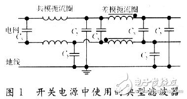
Due to the large capacity of the filter capacitor in the original power supply circuit, a pulse spike current is generated in the rectifier circuit. This current is composed of a large number of high-order harmonic currents, which causes interference to the power grid. In addition, the switch tube is turned on or off, and the transformer is turned on. The primary coil produces a pulsating current. Due to the high rate of current change, induced currents of different frequencies are generated for the surrounding circuits, including differential mode and common mode interference signals, which can be transmitted to other lines of the power grid and interfere with other electronic devices through two power lines. The differential mode filtering part in the figure can reduce the differential mode interference signal inside the switching power supply, and can greatly attenuate the electromagnetic interference signal generated when the device itself works to the power grid. According to the law of electromagnetic induction, E=Ldi/dt is obtained, where: E is the voltage drop across L; L is the inductance; di/dt is the current change rate. Obviously, the smaller the current change rate is, the larger the inductance is required.
The pulse current loop generates a common mode signal by electromagnetically inducing an interference signal generated by another circuit and a circuit composed of a ground or a casing; a strong electric field is generated between the collector of the switching tube and other circuits in the switching power supply circuit, and the circuit generates a displacement current. And this displacement current also belongs to the common mode interference signal. The common mode filter in Figure 1 is used to suppress common mode interference and to be attenuated.
1.1.2 Active Filter Technology
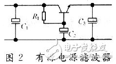
Active filtering technology is an effective method to suppress common mode interference. The method adopted by the method from the noise source (as shown in Figure 2), the basic idea is to try to take out a compensation signal with the same magnitude and opposite phase from the main circuit to balance the original interference signal to achieve Reduce the level of interference. As shown in Fig. 2, the current amplification of the transistor is used to filter the current in the base circuit by folding the current of the emitter to the base. The filter composed of R1 and C2 makes the base ripple small, so the ripple of the emitter is also small. Since the capacity of C2 is less than C3, the volume of the capacitor is reduced. This method is only suitable for low voltage and low power power supplies. In addition, frequency characteristics, withstand voltage performance, rated current, impedance characteristics, shielding, and reliability should be noted when designing and selecting filters. The installation location of the filter should be appropriate and the installation method should be correct to achieve the desired filtering effect on the interference.
1.2 Shielding technology and grounding technology
The shielding technology can effectively suppress the electromagnetic radiation interference of the switching power supply. Shielding is generally divided into two types: one is electrostatic shielding, which is mainly used to prevent the influence of electrostatic field and constant magnetic field; the other is electromagnetic shielding, which is mainly used to prevent the influence of alternating electric field, magnetic field and alternating electromagnetic field. Shielding technology is divided into shielding for electromagnetic wave parts and shielding of components affected by electromagnetic waves. In a switching power supply, a component that can emit electromagnetic waves refers to a transformer, an inductor, a power device, etc., and a copper plate or an iron plate is usually used as a shield around it to attenuate electromagnetic waves.
In addition, in order to suppress the radiation generated by the switching power supply to diverge to the outside, in order to reduce the influence of electromagnetic interference on other electronic devices, overall shielding should be adopted. The shield can be processed completely in accordance with the method of shielding the magnetic field, and then the entire shield can be integrated with the casing and the ground of the system to effectively shield the electromagnetic field. However, when using the integral shielding, electromagnetic leakage at the joint of the shielding material, the input/output terminal of the electric wire, and the outlet of the electric wire should be fully considered, and the heat dissipation is not easy, and the structural cost is greatly increased.
In order to enable the electromagnetic shielding to simultaneously exert the role of electrostatic shielding, strengthen the shielding effect, and at the same time ensure the safety of the human body and equipment, the system should be connected to the earth, which is the grounding technology. Grounding is the design of a conductive path between a selected point in the system and a ground plane. This process is crucial. The correct combination of grounding and shielding can better solve the electromagnetic interference problem and improve the anti-interference ability of electronic products.
1.3 PCB design technology
In order to better suppress the electromagnetic interference of the switching power supply, the anti-jamming technology of the printed circuit board (PCB) is particularly important. To reduce PCB electromagnetic emissions and crosstalk between circuits on the PCB, pay close attention to PCB layout, wiring, and grounding. For example, reducing radiation interference is to reduce the access area, reduce the loop area of ​​the interference source and the sensitive circuit, and adopt electrostatic shielding. To suppress the coupling between the electric field and the magnetic field, the distance between the lines should be increased as much as possible.
Grounding in switching power supplies is an important method of suppressing interference. There are three basic types of grounding: safety grounding, working grounding and shielding grounding. The ground wire design should pay attention to the following points: the AC power ground is separated from the DC power ground; the power ground is separated from the weak power ground; the analog circuit is separated from the power ground of the digital circuit; the ground wire is as thick as possible.
1.4 Spread Spectrum Modulation Technology
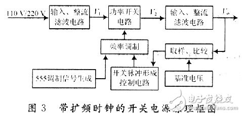
For a periodic signal, especially a square wave, its energy is mainly distributed in the fundamental frequency signal and harmonic components, and the harmonic energy decreases with the increase of the frequency. Since the bandwidth of the nth harmonic is n times the bandwidth of the fundamental frequency, the harmonic energy is distributed over a wider frequency range by the spread spectrum technique. As the fundamental frequency and the harmonic energy are reduced, the emission intensity should also be reduced accordingly. To use the spread spectrum clock signal in the switching power supply, the pulse signal output from the power switch pulse control circuit needs to be modulated to form a spread spectrum clock (as shown in FIG. 3). Compared with the traditional method, the use of spread spectrum technology to optimize the switching power supply EMI is efficient and reliable, without the need to increase the bulk of the filter components and the cumbersome shielding process, and does not have any negative impact on the efficiency of the power supply.
1.5 Adding a power factor correction (PFC) network to the primary rectifier circuit
For the DC stabilized power supply, the grid voltage is directly rectified by the rectifier circuit after being stepped down by the transformer, so the harmonic component generated in the rectification process directly affects the waveform of the AC grid, causing waveform distortion and low power factor. In order to solve the input current waveform distortion and reduce the current harmonic content, it is necessary to apply power factor correction (PFC) technology to the switching power supply. PFC technology makes the current waveform follow the voltage waveform, and corrects the current waveform to an approximate sine wave, which reduces the current harmonic content, improves the input characteristics of the bridge rectifier capacitor filter circuit, and improves the power factor of the switching power supply. The passive power factor correction circuit uses a component such as an inductor and a capacitor to form a filter, and the input current waveform is phase-shifted and shaped to improve the power factor. The active power factor correction circuit realizes the sinusoidalization of the AC input current according to the principle that the control circuit forces the input AC current waveform to track the input AC voltage waveform, and is synchronized with the AC input voltage. Both methods increase the power factor, the latter effect is more obvious, but the circuit is complicated.
2 Conclusion
The design method of this paper is correct, the simulation results are normal, and some problems existing in the traditional scheme are overcome, and the suppression technology of electromagnetic interference is further optimized. From the perspective of the mechanism of electromagnetic interference generated by switching power supplies, there are many ways to suppress electromagnetic interference. In addition to the main methods analyzed in this paper, optical isolators, LSA series surge absorbers, and soft switching technologies can also be used. The purpose of suppressing the electromagnetic interference of the switching power supply is to enable it to be effectively applied in various fields while minimizing electromagnetic pollution and achieving effective treatment of electromagnetic pollution problems. In the actual design, all kinds of electromagnetic interference of the switching power supply should be fully considered, and a variety of methods for suppressing electromagnetic interference should be used to comprehensively utilize, so that electromagnetic interference is minimized, thereby improving the quality and reliability of the electronic product.
10Kv Steel Pole,Metal Pole,Steel Pole
Jiangsu Baojuhe Science and Technology Co.,Ltd. , https://www.galvanizedsteelpole.com