In today's rapidly evolving automotive lighting market, the role of LED drivers is particularly important: to provide car manufacturers with more energy-efficient options to meet consumer fuel economy requirements, improve visibility safety to reduce or avoid traffic accidents, and create personalities. The atmosphere of the vehicle reaches the consumer's unique styling expectations for the car... In the next 8 years, the overall annual growth rate of the automotive lighting system will reach 10%, and the market has great potential, and the drive for such systems will also have Similar growth.
Driver requirements for automotive lighting
LEDs are devices that change brightness based on current, while LED drivers provide a constant light output by adjusting the power of an LED or string of LEDs. Each automotive lighting solution requires a unique drive design that requires engineers to select the right LED driver for their specific application to maximize energy efficiency based on different requirements such as series or parallel, high or low power, and cost or function.
The factors that determine which LED driver is best for its application include:
- The total LED power of each function? - This is the key to determining the topology of the LED driver.
- Electronic ambient temperature? - For example, taillights require brighter LEDs, and it is better to choose a more energy efficient switch driver instead of a high power linear driver to keep cooling at higher power levels.
- Change the flexibility of LED configuration - Light adjustment can be done using a variety of brightness methods such as reference voltage control and pulse width modulation control. Wide work
The power range provides the power configuration and the number of LEDs that can be driven.
- Supported features - such as auto dimming, individual LED controls, color changes.
- Supported troubleshooting and compliance with safety standards - such as thermal alarms, thermal shutdown, open/short circuit, overcurrent protection, over/under voltage and single LED failure.
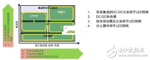
Figure 1: Driver solution for LED lighting
Future lighting drivers will need to have the following factors to support the automotive manufacturer's system requirements:
- Scalable, with flexible hardware to support different automotive applications and requirements to be launched;
- There are different drive requirements in the same module: high pressure gas discharge lamp (HID), LED, etc.;
- As the drive adds more functionality, consider adding diagnostics;
- Reliable LED current control for improved drive reliability.
Automotive lighting innovation
Automotive lighting applications will proliferate inside and outside the car, and lighting systems will become more popular in all automotive segments. The expansion of the market will promote more silicon development.
(1) Today's automotive interior lighting
Most of today's automotive interior lighting uses white LED drivers and RGB red, green and blue programmable drivers.
Bright white LEDs are mainly used for ceiling lamps, reading lamps, cargo compartment lights and other applications where brightness is relatively high, but it is different from standard bulbs, providing a warm and comfortable atmosphere for the driver. Its dimming slope characteristics can be generated. Unique and differentiated shapes and effects. ON Semiconductor offers discrete or constant current stabilized silicon solutions for this type of application.
RGB and white LEDs complement each other, and their development is driven by the power of the vehicle to be personalized, used as a programmable internal light source, including special effects such as instrument panel, center console, navigation/audio and other regional lighting and ambient lights. The color accuracy needs to be calibrated, and the separate LIN corresponds to an RGB, plus regional dimming, which are important features that meet the requirements of automotive manufacturers. ON Semiconductor offers a Linear System Basis Chip (SBC) for this type of application, and the SBC interface provides all the functions of driving RGB LEDs via the LIN bus.
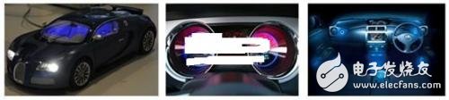
Figure 2: RGB driver for automotive interior lighting
(2) Today's automotive exterior lighting - taillights
From the single LED in the past to the current opaque and uniform light row, from the animated signal to the swept flashing light, the driver is an important part of the evolution of the car's taillights. In addition to continuous innovation in the appearance of cars such as shapes and images, Increasing the safety factor, and supporting start-stop pressure drop, and adaptive ambient lighting conditions are key to meeting the energy requirements of automotive manufacturers and governments. For such applications, ON Semiconductor offers linear current regulators and controllers.
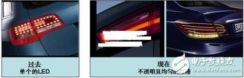
Figure 3: Car taillights
(3) Today's automotive exterior lighting - headlights
LED headlamps are commonly used in daytime running lights (DRL). The two most common solutions are light guide LEDs and LED strings (see Figure 4). These DRL applications not only provide better visibility to oncoming vehicles, but car manufacturers also rely on the flexibility of LEDs and LED drivers to personalize their vehicles and build a unique "visual" brand.

Figure 4. Two common scenarios for LED headlamps applied to DRL
Advanced headlamps for luxury cars are not limited to DRL, high beam and low beam. Automotive manufacturers can also choose LED turn signals, LED fog lights and high-speed street spotlights, as well as a combination of HID and LED solutions. The headlight system, and even the future full LED lights. Driven by a more personalized, safer and more energy-efficient trend, consider modularizing the platform, from low-cost “entry-level low beam†to high-end full-featured “advanced lighting systemâ€, offering a variety of automotive manufacturers. Innovation.
In terms of cost, advanced lighting systems are more expensive than standard lighting systems, but can be reduced in function to cater to low-cost cars. In addition, it is scalable and can be expanded as needed for a wide range of vehicles.
ON Semiconductor offers dual-channel LED drivers and stepper motor drivers for adaptive headlamp systems (AFS). These systems further enhance safety levels and provide lighting units that can be moved and rotated depending on the driving environment, speed and vehicle load. Dual-channel LED driver features include integrated power LEDs, system-on-a-chip, and an up to 125 dc ambiance for medium to high total power. The stepper motor driver offers bipolar stepper drive, microstepping, stall detection, LIN, I2C and SPI interfaces, and features up to 125 dc.
Future automotive lighting solutions - pixel / matrix headlights
Moving from motor control to the use of pixel/matrix headlight systems is a major trend in automotive lighting in the future. It uses a modular platform design that offers many advantages over today's headlamp solutions, enhanced by high-tech and innovative designs. The car image supports 50% to 80% or more of the full static glare-free high beam, which adjusts the lighting system according to the environment and the oncoming car, providing the driver with higher visibility in all situations. LED technology, no moving parts, safer and more reliable. In addition, more functions can be expanded due to multiple blank areas, and adjustable illumination power per pixel, and fast switching.
The LED AFS pixel/matrix system consists of LED-specific standard products (ASSP), FETs, LDOs, rectifiers, logic, Zener, protection and more. ON Semiconductor now offers all semiconductor components except microcontrollers. As systems become more standardized, the microcontroller can be embedded into an application-specific integrated circuit (ASIC) to support potential ON Semiconductor single-chip silicon solutions.
ON Semiconductor's NCV78247 pixel/matrix controller capable of driving 4 LED strings, integrated dimming controller, built-in overvoltage/undervoltage, overtemperature, short/open detection (including LED bypass open), SPI interface, output Faults, output segments are configurable, SPI communication and onboard microcontrollers are available (Figure 5).
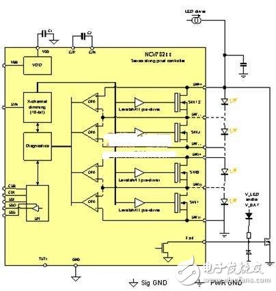
Figure 5. NCV78247 pixel/matrix controller
Conclusion
The automotive lighting driver market will continue to require a driver portfolio that supports everything from the simplest discrete components to the combination technology, providing more possibilities for automotive exterior design and improving driving safety and fuel economy. Pixel/matrix headlights are a key trend for future headlamps.
Product Description
SPD Surge Protective Device,Lightning Surge Protector
Surge Protection Device (SPD)
It is a device used to limiting instant surge voltage and discharge surge current, it at least including a non-linear component.
Surge protective Device Model Selection
With the impact of international information flow, the rapid development of microelectronic science and technology, communication, computer and automatic control technology, make the building start to go for high quality, high functional area, formed a new building style-intelligent building. As inside the intelligent building there are lot of information system, <<Building lightning protection design norm>> GB50057-94(2002 vision)(hereafter brief as <<lightning protection norm>>) put forward the relative requirement to install the surge protective device, to ensure the information system safely and stable running.
SPD essentially is a equipotential connection material, its model selection is according to the different lightning protection area, different lightning electromagnetic pulse critical and different equipotential connection position, decide which kind of SPD used in the area, to achieve the equipotential connection with the common earth electrode. Our statement will based on SPD's maximum discharge current Imax, continuous operating voltage Uc, protection voltage Up, alarm mode etc.
As per << Lightning Protection Norm>> item 6.4.4 stipulation "SPD must can withstand the expected lightning current flow and should confirm to the additional two requirements: the maximum clamp voltage during surge across, capable to extinguish the power frequency follow-on current after lightning current across." That is the value of SPD's max. clamp voltage add its induction voltage of two ends should be same with the system's basic insulation level and the equipment allowed max. surge voltage.
SPD for Power Supply System Series Selection Guide
The installation of SPD at each lightning protection zone, according to the standard of Low Voltage Electrical appearance, make classification of electrical equipment in accordance with the over voltage category, its insulation withstand impulse voltage level can determine the selection of SPD. According to the standard of low voltage electrical appearance, make classification of electrical equipment in accordance with the over voltage category as signal level, loading level, distribution and control level, power supply level. Its insulation withstand impulse voltage level are:1500V,2500V,4000V,6000V. As per to the protected equipment installation position different and the different lightning current of different lightning protection zone, to determine the installation position of SPD for power supply and the break-over capacity.
The installation distance between each level SPD should not more than 10m, the distance between SPD and protected equipment should as short as possible, not more than 10m. If due to limitation of installation position, can't guarantee the installation distance, then need to install decoupling component between each level SPD, make the after class SPD can be protected by the prior class SPD. In the low voltage power supply system, connecting an inductor can achieve the decoupling purpose.
SPD for power supply system specification selection principle
Max. continuous operating voltage: bigger than protected equipment, the system's max. continuous operating voltage.
TT System: Uc≥1.55Uo (Uo is low voltage system to null line voltage)
TN System: Uc≥1.15Uo
IT System: Uc≥1.15Uo(Uo is low voltage system to line voltage)
Voltage Protection Level: less than the insulation withstand impulse voltage of protected equipment
Rated discharge current: determined as per to the lightning situation of the position installed and lightning protection zone.
SP1 Series
Normal Working Conditions
-Altitude not exceed 2000m
-Ambient air temperature:
Normal range: -5ºC~+40ºC
Extend range: -40ºC~+80ºC
-Relative Humidity: 30% - 90% under indoor temperature condition
- At the place without obviously shaking and shock vibration
- Non-explosion danger medium, non-corrosion gas and dust ( including conductive dust)
Classification
-As per Nominal Discharge Current:
5,10,20,30,40,60KA(8/20µs)
- As per Maximum continuous operating voltage:
275V,320V,385V,420V,440V,460V
- As per to poles
1P,1P+N,2P,3P,3P+N,4P
- As per auxiliary functions:
a. With remote signal output ( remote alarm function)
b. Without remote signal output
Selection Principle
- The continuous applied voltage on the two terminals of SPD should not more than the maximum continuous operating voltage Uc value;
- The voltage protection level Up of SPD should less than the maximum impulse withstand voltage of the protected equipment;
- As per to the different earthing system and protection mode to select the specification accordingly;
Product Features
1, built-in over-current overheating, temperature control circuit technology.
2, the module design, easy installation, online replacement.
3, low leakage current, fast response time, low residual voltage.
4, alarm indication device, green (normal) v red (fault).
| Model/Technical Parameters | WR-B60 | WR-B80 | WR-B100 | WR-B120 | WR-B150 |
| Rated Operating Voltage Un (V ~) | 220V 380V | 220V 380V | 220V 380V | 220V 380V | 220V 380V |
| Maximum Continuous Operating Voltage Uc (V ~) kV | 385V 420V | 385V 420V | 385V 420V | 385V 420V | 385V 420V |
| Voltage Protection Level Up (V ~) kV | ≤1.8≤2.2 | ≤2.4≤2.5 | ≤2.5≤3.2 | ≤3.4≤3.7 | ≤4.0≤4.5 |
|
Maximum Discharge Current Imax(8/μ20μs)kA |
60 | 80 | 100 | 120 | 150 |
|
Nominal Discharge Current In(8/μ20μs)kA |
30 | 40 | 60 | 80 | 100 |
| Response Time | <25 | <100 | |||
| L/N(mm²)The Cross Section Of L/N Line | 16,25 | 16,25 | 16,25 | 16,25 | 25,35 |
| PE (mm²)The Cross Section Of PE Line | 16,25 | 25,35 | 25,35 | 25,35 | 35 |
| Fuse or Switch (A) | 63A | 63A | 63A,100A | 63A,100A | 63A,125A |
| The Line Section of Communication and Alarm (mm²) | ≥ 1.5 | ||||
|
Operating Environment-C |
(-40ºC~-+85ºC) | ||||
| Relative humidity 25 ºC | ≤95% | ||||
| installation | Standard Rail35mm | ||||
| Material of Outer Covering | Fiber Glass Reinforced Plastic | ||||
Surge Protector SPD,Surge Protection Device SPD,SPD
Wenzhou Korlen Electric Appliances Co., Ltd. , https://www.korlen-electric.com