Cameras and other sensors are often used in measurement systems, and synchronization is required between the two. This example describes an aerial photography system that has a camera that includes a CCD (charge coupled device) image sensor, an inertial measurement unit, and a GPS (Global Positioning System) unit. The synthesized circuit provides a trigger signal that synchronizes the measurement at the optimum rate. GPS provides information about the location of the space, and the inertial measurement unit provides information about the spatial orientation. The unit includes a gyroscope, a magnetometer, and an accelerometer that provides angle and acceleration measurements for a three-axis vector.
Figure 1 shows a system for obtaining aerial photographs. It includes: four Atmel area scanning CCD image modules, a linear image sensor module, two Dalsa PCI (peripheral component interconnect) frame capture cards, a measurement unit, a clock conditioning circuit, and a microcontroller. During development, the trigger signal is viewed using a Tektronix digital oscilloscope.
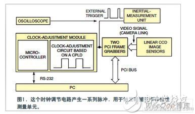
The trigger signal used to synchronize the sensors is the key to this measurement system. The clock adjustment circuit sends an external trigger pulse to the frame capture card to generate a trigger signal for the system. A video module containing an image sensor receives a trigger signal from a frame capture card. Each frame capture card captures an image, stores it in the onboard memory, and then captures the next image.
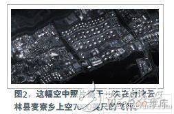
External trigger pulses also control the sensor, GPS and inertial measurement unit. Figure 2 shows a photograph of 7000 feet above the Maizi Township in Yunlin County, Taiwan, using an external trigger circuit to complete the drive and combination of the linear sensor and measurement unit.
The circuit must change the frequency of the external trigger clock to get the best frame rate. The CCD sensor in the linear image sensor module has 12,288 pixels, each of which has a size of 5 mm x 5 mm, and produces an image of about 500 lines/frame. The maximum output rate of the CCD image sensor is 320 Mpixels/second. The image data is sent to the frame capture card via a Camera Link interface, which sends the image to a PC over the PCI bus.
The clock adjustment circuit generates an externally triggered clock pulse. The circuit uses an Altera CPLD (Complex Programmable Logic Device), which uses Altera's development software to simulate trigger signals and design circuits. The clock conditioning circuit provides up to 15 trigger signal frequencies to the system.
The system's Atmel microcontroller has 256 bytes of RAM and 8k bytes of programmable flash for program storage. The microcontroller communicates with the PC via an RS-232 interface, which can also be used to receive commands and report on their current status. This handshake process involves generating decoding and encoding parameters for the trigger signal. The microcontroller also sends instructions to the digital timing adjustment circuitry; these instructions can change the pulse frequency of the external trigger.
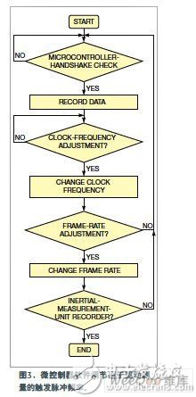
The 15 frame trigger frequencies can be used to adjust the frame rate of the CCD image module. The external trigger signal is also used to trigger the measurement unit to record and store spatial parameters. Figure 3 shows the algorithm for finding the best trigger frequency. The frame rate is proportional to the trigger frequency.
The inertial measurement unit is a key sensor in the system and must have a direct correlation between it and the frame capture card. If the external trigger frequency is 1 kHz, each of the two frame capture cards captures 1000 frames/second and the unit sample rate is 1k samples/second. Experimental results of aerial photography show that the system successfully synchronizes all sensors.
Eel Epi-Wafer ,Edge-Emitting Lasers Epi-Wafer ,4 Inch Gaas Wafer ,Edge Emitting Laser Wafer Chip
AcePhotonics Co.,Ltd. , https://www.acephotonics.com