How to suppress electromagnetic interference has always been a problem that cannot be ignored in the design of switching power supply modules. It is not only related to the reliability of the power module itself, but also related to the safety and stability of the entire application system. The full suppression of various noise interferences of the switching power supply module will enable the switching power supply module to be more widely used.
First, the definition of electromagnetic interference
  Electromagnetic Interference (EMI) refers to any electromagnetic phenomenon in which conduction or electromagnetic fields are accompanied by voltage and current, which may degrade the performance of a device, device or system, or may adversely affect biological or material. .
Second, the generation of electromagnetic interference
1. The generation of electromagnetic interference
The source of disturbance, sensitive equipment and coupling means are called the three elements of electromagnetic interference. For switching power supply modules, noise is generated by a sharp change in current or voltage, ie, di/dt or dv/dt is large, so devices operating at high power and high frequency are sources of EMI noise. Specifically, its main sources are:
(1) Externally coupled interference (mainly generated at the input and output);
(2) switch tube;
(3) transformers;
(4) diode;
(5) Energy storage inductance;
(6) Circuit interference caused by unreasonable PCB layout and routing.
Third, the countermeasures to suppress electromagnetic interference
People always try to remove one of the three elements of electromagnetic interference: shielding out sources of disturbance, isolating sensitive equipment, or cutting off coupling paths. From the perspective of energy, electromagnetic interference is an energy that cannot be prevented from being generated. Only certain methods can be used to reduce its interference with the system. The available methods can be divided into two categories: one is to let the energy drain off; the other is to block the energy outside. It can be said that one method is to reduce the amplitude of its production, and the other is to cut off its propagation path.
The following is an analysis of specific aspects:
1. Coupling of external interference (input and output)
(1) Input
The input is the entrance of the entire power supply, and the noise inside the power supply can also be transmitted to the outside, causing interference to the outside world. A commonly used strategy is to filter noise and interference at the input plus X capacitor, Y capacitor, differential mode inductor, and common mode inductor. Figure 1 is a relatively common EMI filter circuit.
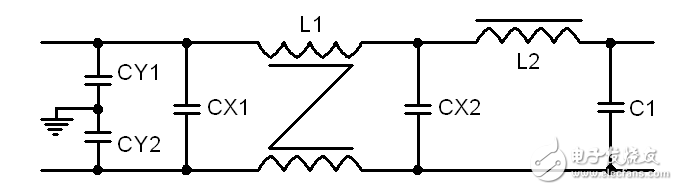
Figure 1 EMI filter circuit
The filter circuit composed of L1, CY1 and CY2 can suppress the common mode interference signal existing on the power line. When a common mode interference current flows through the coil, due to the same direction of the common mode current, a co-directional magnetic field is generated in the coil to increase the inductance of the coil, so that the coil exhibits high impedance and produces a strong damping effect. To attenuate common mode interference. The differential mode inductor L2 and the X capacitor form a low-pass filter that rejects differential mode interference on the power line.
(2) Output
For the output, especially in the case of long output leads, after the power module is matched with the system, some noise interference inside the power supply may be coupled to the outside by the output line, interfering with other powered devices. The best way to do this is to add some common mode filtering and differential mode filtering as well as the interference to the input. In addition, it is also possible to string the magnetic bead ring on the output line; use twisted pair or shielded wire to achieve the purpose of suppressing EMI interference.
2, switch tube
During the operation of the power module, due to the existence of the junction capacitance of the switch, the switch will produce burrs and spikes during fast switching, so that some of the transmission or transmission will occur. In addition, the junction capacitance of the switching transistor and the winding leakage inductance of the transformer may also generate resonance and cause interference.
The countermeasures that can be used for this are:
(1) The D-pole and the G-pole of the switch tube are added with a magnetic bead ring, which is equivalent to adding a small inductance to reduce the current change rate of the switch tube, thereby achieving the purpose of reducing the peak.
(2) Add a snubber circuit at the switch tube or use soft-switching technology to reduce the peak of the switch tube during fast operation, so that its voltage or current can rise slowly.
(3) When the voltage difference between the switch tube and the peripheral components is reduced, the degree of charge of the junction capacitor of the switch tube is reduced to some extent.
(4) Increase the G-pole drive resistance of the switch.
3, transformer
The transformer is the energy storage component of the power module, which may cause noise interference during the charging and discharging process of energy. The leakage inductance can form an oscillating circuit with the distributed capacitance in the circuit, so that the circuit generates high frequency oscillation and radiates electromagnetic energy outward, causing electromagnetic interference. The potential difference between the primary winding and the secondary winding also produces a high frequency variation, which is coupled by parasitic capacitance, resulting in a common mode conducted EMI current disturbance flowing between the primary side and the secondary side.
The countermeasures that can be used for this are:
(1) Transformer plus shielding.
Shielding can be divided into electrical shielding and magnetic shielding. The main function of electrical shielding is to isolate the primary interference signal from the secondary. A layer of copper foil (internal shield) can be placed between the primary and secondary, but the head and tail cannot be short-circuited, and the copper foil should be grounded, so that a capacitor is formed between the primary winding and the copper foil, and the common mode conduction interference signal passes through the capacitor-copper. The foil-grounding forms a loop that does not enter the secondary winding and acts as an electrical shield. Magnetic shielding is the copper foil (outer shield) that is connected end to end in the outer cable of the transformer. The copper foil is a good conductor. When the high-frequency alternating leakage flux passes through the copper foil, eddy current is generated, and the direction of the magnetic field generated by the eddy current is exactly opposite to the direction of the leakage flux, and part of the leakage flux can be cancelled.
(2) The sandwich winding method can reduce the high frequency interference of the primary coupling to the transformer core. Since the primary is far away from the core and the secondary voltage is low, the high frequency interference caused is small.
(3) Reduce the working frequency and slow the rapid charging and discharging of energy.
(4) Reliable isolation of the primary side and the secondary side, and the ground capacitance between the primary side and the secondary side is connected to the Y capacitor.
(5) Minimize the leakage inductance of the transformer and improve the distribution parameters of the circuit to reduce the interference to a certain extent.
4, diode
During the fast turn-off and turn-on of the diode, there will be spikes, especially rectifier diodes. During the reverse recovery process, the parasitic inductance and capacitance of the circuit will oscillate at high frequency, causing electromagnetic interference.
The countermeasures that can be used for this are:
(1) Add the RC snubber circuit to allow the diode's energy to bleed gently.
(2) A magnetic bead ring is placed on the cathode pin so that its current cannot be abruptly changed to reduce the peak.
5, energy storage inductance
(1) Similar to a transformer, it can be shielded.
(2) Adjust its parameters to avoid oscillation with the capacitance of the loop.
6, PCB layout and routing
Accurately speaking, the PCB is the coupling channel of the above interference source, and the advantages and disadvantages of the PCB directly correspond to the suppression of the above EMI source. At the same time, the layout and wiring of the devices on the PCB are unreasonable, which will cause EMI interference.
The countermeasures that can be used for this are:
(1) The most effective way to reduce interference is to reduce the area of ​​each current loop (magnetic field interference) and the area and length of the live conductor (electric field interference).
(2) Different ground lines in the circuit, especially analog ground and digital ground, are to be separated.
(3) The power and ground lines of the PCB are as wide as possible to reduce the line impedance, thereby reducing the interference noise caused by the common impedance.
(4) Impedance matching must be considered for the line transmitting the signal.
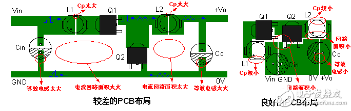
Figure 2 Comparison of two PCB layouts
For small DC-DC power modules, the usual practice is to build electromagnetic circuits to suppress electromagnetic interference to ensure the reliability of the application system. The EMC recommended circuit is shown in Figure 2, with 1 part for EMS testing and 2 for EMI filtering.
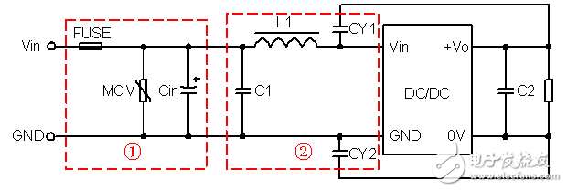
Figure 3 DC-DC power supply module EMC recommended circuit
These products do not need any power supply to be functioned. The entire range of power systems offered by us is manufactured with beat quality material in compliance with the well-defined industrial quality standards. These solar products suit well with the utmost needs of clients and can be customized as per their specifications and requirements. Our solar power systems comprise MNES specifications. The broad range of these products includes DC fans, portable lights, lighting systems, portable lanterns, CFL lamps, and other appliances.
20W 12Ah Solar Home Power,12Ah Solar Home Power,20W Solar Home Power
Yangzhou Bright Solar Solutions Co., Ltd. , https://www.solarlights.pl