Applications based on radar (RADAR) and camera design are entering the field of automotive driving safety. Initially, advanced driver assistance systems (ADAS) such as adaptive cruise control and road departure warning were just some of the most convenient features, and now they play a more proactive role in vehicle control, supporting the implementation of lane maintenance assistance (LKA). . Previous high-performance central processing units (CPUs) were considered the most suitable components for these applications, but the need for the vehicle to consider both computing performance and low power consumption prompted engineers to move to field-programmable gate array (FPGA) components.
This article refers to the address: http://
ADAS is required to meet special functional safety requirements. In 2011, ISO issued the ISO26262 standard for passenger cars with a load of less than 3.5 tons to reduce the risk of danger after system failure. This standard requires a rigorous design process to detect random hardware failures during application execution to reduce systemic failures.
Enhancing ADAS Functional Safety FPGA SoCs are favored
Application developers define specific safety objectives and assign a corresponding Automotive Safety Integrity Level (ASIL) to each target. For the highest level of ASIL-D in the application, the requirements that each component should meet from development to operation to end of life are usually defined. Figure 1 shows the current range of ASIL that ADAS should meet in terms of customer demand.
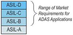
Figure 1 ASIL specification level required for ADAS
ASIL-B is the lowest level on the market, while some applications require ASIL-D to support certain features. More and more ADAS applications have stricter requirements for ASIL. In some implementations, the generic ASIL or project (system) level of a component introduces unnecessary complexity, affecting development costs and schedule. After analyzing the system concept and drawing out the security concepts and requirements, the application can be divided into several different steps with different ASILs. As a result, the system design can be more easily realized and the efficiency is higher.
For example, the front camera application uses an image sensor that is common in ADAS, such as the high-level structure shown in Figure 2. An image sensor is connected to the image processor, which can be an Altera Cyclone FPGA system single-chip (SoC) or other solution. The signal processing link and data stream are divided into four parts. First, the underlying processing is performed at the pixel level by transforming the image into a more practical representation. Then, the image or the block image is subjected to intermediate level processing, and the corresponding algorithm is used to extract features such as edges. In the next step, high-order processing is performed, the data of each frame is extracted, and the targets are detected and classified. The system then tracks the target and communicates with the brake or steering engine control unit (ECU) if action is required.
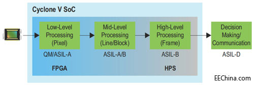
Figure 2 High-order single front camera ADAS
In addition to the very efficient implementation of low-level and intermediate-level processing on the FPGA, users can also implement some intermediate-level processing in the processing cores of the Cyclone V-Series FPGA SoC Hard Core Processor System (HPS) Cortex-A9. The high-level processing is primarily a handle that can be mapped to one or two Cortex-A9s in the HPS. The final step in processing the link is target tracking and judgment, which can be done on an external microcontroller (MCU).
Throughout the process, engineers can streamline input data to get more meaningful data, and data reduction means increasing safety thresholds. Therefore, the underlying implementation can be divided into quality management (QM) or underlying ASIL (eg ASIL-A). The reason for this is because the failures that occur during a single pixel have little effect on the performance of subsequent algorithms and can therefore be ignored. In this example, assuming that the intermediate level processing conforms to ASIL-A or ASIL-B, the higher-order processing functions that identify and classify the target should conform to ASIL-B. After classifying the target, a target table is generated and provided to the microcontroller for target tracking and judgment. This is the most critical part of the signal link, and we think it should be in line with ASIL-D, which has a direct impact on the car's behavior.
Realize hierarchical security processing FPGA and design reliability/efficiency
In such applications, it is best to perform a more comprehensive analysis of the data stream, and each level of security critical definition has a direct impact on the performance of the entire system. Too high security requirements for the previous level of operation can make it difficult to meet system performance goals and have little impact on overall system security. However, the underlying layer of the processing link also has a failure, which has a large impact on the system security function. For example, a permanent failure of the underlying processing function may cause permanent damage to the data at the upper layer, which is easily detected through the plausibility check. The impact on system performance is relatively small.
Figure 3 shows a high level block diagram of an example of a single front camera system. The Cyclone V SoC is powered by an external power management circuit. When the supply voltage is not within the rated operating range, a separate voltage monitoring function will generate a reset. The external non-volatile memory is connected to the quad serial peripheral interface (Quad SPI). Modules, applications are loaded during system startup, and are used when configuring the FPGA. We use double data rate (DDR) memory to execute application code, store data and image frame frames, connect external microcontrollers via SPI, target detection and final judgment, and utilize controller area network (CAN) interface with The other parts of the car chassis communicate.
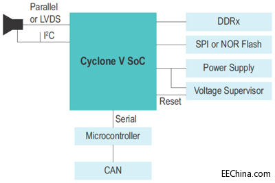
Figure 3 Single front camera system example
The image processor module used in this application is shown in Figure 4. The video port receives the data from the image sensor and transmits it to the image processing module. This module is equivalent to the underlying image processing level. In this example, the data is transmitted through the FPGA to the HPS (F2H) bridge after passing through the image processing module. Into the DDR memory, you can also transfer to the next level, achieving higher efficiency. The second level is intermediate level processing, which is performed by various image processing modules. The HPS to FPGA (H2F) bridge is used to read the data previously stored in the DDR memory and write it to the DDR memory again. In this example, the high-level processing hierarchy is done by HPS.
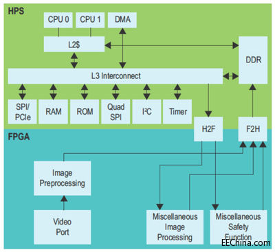
Figure 4 Cyclone V SoC circuit architecture diagram
Play a programmable benefit FPGA full-scale detection system failure
The next paragraph will explain the diagnostic functions used to detect faults in different areas of the design. Some diagnostic functions can detect permanent faults, while others can only detect temporary faults, and some can detect various faults. A temporary fault is a fault that occurs after it disappears. For this type of situation, the designer should consider the faults that occur in memory when implementing certain functions, and the faults that may occur in the logic when implementing the function.
Before the application software uses the image sensor, the engineer should configure it to continually modify the configuration to accommodate different lighting conditions during application execution. Image sensors are critical to application operations. Therefore, it is recommended to perform at least one check of their configuration during Fault Tolerant Interval (FTTI), which does not necessarily cover all possible sensor failures, but can manage the configuration buffer group (Table 1). ).
Is mainly used for adult health care products and toys micro vibration motor is a Dc Motor, the motor shaft with an eccentric wheel, when the motor rotation, eccentric circle particle is not turn the heart of the motor, make motor is constantly out of balance state, caused by inertial effect.
Characteristics: small volume, strong vibration;
Features: small size, fast speed, stable performance, low price, can use battery drive,Can change the different materials of the pendulum head


Method of use: the best stable in horizontal plane, installed on the dc vibration motor output shaft parts, cannot use a hammer to knock, knock prone to press into the dc vibration motor drive, may cause damage to internal components, and cannot be used in the case of blocked.

Operating temperature range:
vibration motor should be used at a temperature of -10~60℃.
The figures stated in the catalog specifications are based on use at ordinary room temperature catalog specifications re based on use at ordinary room temperature (approximately20~25℃.
If a vibration motor is used outside the prescribed temperature range,the grease on the gearhead area will become unable to function normally and the motor will become unable to start.Depending on the temperature conditions ,it may be possible to deal with them by changing the grease of the motor's parts.Please feel free to consult with us about this.
Storage temperature range:
vibration motor should be stored ta a temperature of -15~65℃.
In case of storage outside this range,the grease on the gearhead area will become unable to function normally and the motor will become unable to start.
Service life:
The longevity of vibration motor is greatly affected by the load conditions , the mode of operation,the environment of use ,etc.Therefore,it is necessary to check the conditions under which the product will actually be used .The following conditions will have a negative effect on longevity.Please consult with us should any of them apply.
â—Use with a load that exceeds the rated torque
â—Frequent starting
â—Momentary reversals of turning direction
â—Impact loads
â—Long-term continuous operation
â—Forced turning using the output shaft
â—Use in which the permitted overhang load or the permitted thrust load is exceeded
â—A pulse drive ,e.g.,a short break,counter electromotive force,PWM control
â—Use of a voltage that is nonstandard as regards the rated voltage
â—Use outside the prescribed temperature or relative-humidity range,or in a special environment.
â—Please consult with us about these or any other conditions of use that may apply,so that we can be sure that you select the most appropriate model.
when it come to volume production,we're a major player as well .each month,we rurn out 600000 units,all of which are compliant with the rohs directive.Have any questions or special needed, please contact us, we have the engineer group and best sales department to service to you Looking forward to your inquiry. Welcome to our factory.

Vibration Motor
Vibration Motor,Small Powerful Vibration Motor,220V Vibration Motor,Electric Motor For Vibrating
Shenzhen Shunchang Motor Co., LTD. , https://www.scgearmotor.com