introduction
MEMS1 (Micro Electro Mechanical System) utilizes manufacturing process facilities developed specifically for semiconductor integrated circuits to achieve manufacturing. The realization method of the microelectromechanical structure is to etch a specific pattern on the semiconductor substrate to realize the sensor unit or a mechanical actuator that can move a few micrometers. MEMS pressure sensors are the first type of mass-produced products. They are now used to monitor the pressure of hundreds of millions of engine manifolds and tires; MEMS accelerometers are used in airbags, roll detection, and car alarm systems. More than 15 years.
MEMS accelerometer 2 is also used for motion sensing in the field of consumer electronics, such as video games and mobile phones. MEMS micromirror optical actuators are used in projectors, HDTVs and digital cinemas. In recent years, MEMS microphone 3 has also begun to enter a broad consumer market, including mobile phones, Bluetooth headsets, personal computers and digital cameras.
This article will discuss some of the key technologies used in MEMS accelerometer products and discuss how these technologies can bring new applications to acoustic sensors.
MEMS accelerometer technology
The core unit of a typical MEMS accelerometer is a movable bar structure consisting of two groups of finger grids: one group is fixed to a physical ground plane on the substrate; the other group is connected to one and mounted to one group On the mass on the spring, the spring can move according to the applied acceleration. The applied acceleration (Figure 1) will change the capacitance between the fixed and moving grid. 4
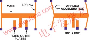
Figure 1: MEMS accelerometer structure.
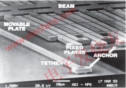
Figure 2: ADXL50 MEMS accelerometer structure.
The size of these MEMS structures is on the order of micrometers (Figure 2), so semiconductor lithography and etching process technologies with extremely high precision are required. MEMS structures are usually formed using single crystal silicon, or polysilicon deposited on the surface of single crystal silicon wafers at extremely high temperatures. With this flexible technology, structures with very different mechanical properties can be formed. One of the mechanical parameters that can be controlled and changed is the spring rate. The mass and structural damping of the sensing unit can also be changed in the design. The sensor can realize acceleration sensing from a few g to hundreds of g, and its bandwidth is up to 20kHz.
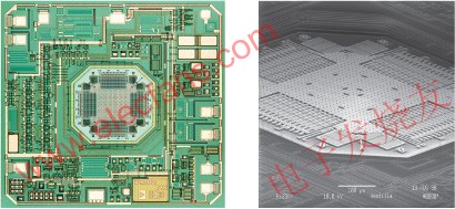
Figure 3: ADXL202 ± 2 g accelerometer.
MEMS sensing units can be connected to signal conditioning circuits located on the same chip (Figure 3) or on different chips (Figure 4). For a single-chip solution, the capacitance of the sensing unit can be as low as 1-2 femtofarads per g, which is equivalent to a measurement resolution of 10-18F! In a two-chip architecture, the capacitance of the MEMS unit must be high enough to Overcome the influence of parasitic capacitance of the connecting line between MEMS and ASIC conditioning circuit. 5
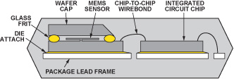
Figure 4: A cross-sectional view of a typical two-chip accelerometer.
Accelerometer as a vibration measurement sensor
The concept of using vibration sensor sensors to pick up sound in musical instruments is not new. 6 Piezoelectric and electromagnetic sensors are the basis of many acoustic pickup applications today. Because the miniature MEMS accelerometers are small in size and mass, they do not affect the instrument in terms of mechanical or mass loads, making them attractive in these applications. But so far, due to the narrow bandwidth of commercial acceleration sensors, its application is still relatively limited.
Some recent breakthroughs in accelerometer technology have resulted in mass production of very small accelerometers with very high bandwidth. The ADXL0017 (Figure 5) high-g (± 70g to ± 500g) single-axis accelerometer in a 5mm × 5mm × 2mm package has a bandwidth of up to 22kHz, making it ideal for monitoring vibration. The motor can be determined by detecting changes in the device ’s acoustic characteristics Or “health†status of other industrial equipment. In the early stages of bearing wear, a high-g vibration sensor attached to the system base can detect a clear vibration signal in the audio range. This special sensor used to measure up to 10g is obviously not sensitive enough to be used as an acoustic vibration sensor for musical instruments. The ideal acoustic sensor needs to measure the response in all three axes, but it can only sense single-axis motion. However, it has been proved that using MEMS technology can already achieve acceleration sensors within the full audio bandwidth.
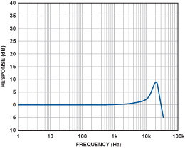
Figure 5: Frequency response curve of ADXL001.
Low-g accelerometers can measure accelerations down to the g-thousandth of a g, but the bandwidth is generally limited to about 5 kHz. In fact, the reason for this limitation may be that there are too few commercial applications that require high bandwidth (main applications include acceleration detection caused by human motion or gravity), so there is a lack of motivation to develop sensors that are particularly suitable for audio frequency band measurement.
A 3-axis accelerometer has three independent outputs that measure the acceleration on the X, Y, and Z axes in Cartesian coordinates. The ADXL3308 3-axis low-g accelerometer has a wider effective bandwidth than traditional low-g accelerometers. Its bandwidth is up to 6 kHz on the X and Y axes, and around 1 kHz on the Z axis. Although not ideal, this bandwidth has enabled the device to obtain useful information on the audio segment. The output is an analog signal, so it is easy to use in standard recording equipment. The device uses a standard surface mount package, making full use of mature semiconductor manufacturing equipment. The package size is 4mm × 4mm × 1.45mm (Figure 6), which can be applied to places that are incredible for traditional accelerometer technology. Its volume is very small and will not cause changes in the mass load or other aspects of the system under test. The following will explain why the low-g accelerometer can be used for acoustic pickup applications of guitars.
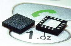
Figure 6: MEMS accelerometer, package size is 4mm × 4mm × 1.45mm.
Voice feedback problem
Danish scientist Soren Larsen first introduced an omnidirectional condenser dynamic microphone in the mid-nineties of the last century. It was the earliest discovery of the principle of sound feedback (called the Larsen effect). Acoustic feedback has always been a nightmare for acoustic engineers. Few engineers have complete control over it, especially at any performance scene. The Beatles fully felt the impact of this false sound, and then decided to add it to the introductory song of their memorable album "I Feel Good" in 196410. Then Rock 'n' Roll began to use it like a taming beast, using voice feedback to add a refreshing feature to rock music. Electric guitar players, such as Pete Townshend and Jimi Hendrix, deliberately placed the guitar close to the speaker to use acoustic feedback. As this trend subsided, audio engineers continued to work hard to eliminate the unpleasant auditory effects caused by sound feedback, especially during live performances. In an audition room that is perfectly designed and treated with special acoustics, omnidirectional microphones can be used to perfectly record instrument sounds, almost reaching an amazing sense of presence and fidelity. Artists who understand and cherish this point have been tirelessly seeking how to reproduce this effect on the stage. Although hoping to record live performances in the same quality as the studio has always been the dream of musicians, it is actually impossible. Even if the best sound equipment is used on the stage, the stage has undergone excellent acoustic design. Sound engineers can use all kinds of reverberation proficiently and can have the best equipment and tools. There are insurmountable obstacles: that is voice feedback.
Acoustic pickup
Generally, the use of directional microphones can minimize sound feedback. To some extent this is possible, but it requires tuning engineers to constantly adjust to the changing characteristics of the stage.
Use the pickup to amplify the sound of the instrument. The various technologies used have certain differences, but the basic principle is to directly sense the vibration of the instrument itself, rather than detecting the sound waves it generates in the air. The advantages of this approach are obvious: pickups hardly produce sound feedback because they are not sensitive to the sound waves transmitted in the air. But this method also has many shortcomings: including finding the best sound position on the instrument is extremely difficult, the acoustic characteristics of piezoelectric pickups are far from perfect, and their output impedance is high impedance, so special Musical instrument input or direct boxes. In addition, the volume is also large, which will affect the natural acoustic characteristics of the instrument itself.
Thus, these problems led to the concept of low-quality contact microphones. If we use a surface sensor to measure the acceleration of the instrument body, this is more suitable than a single axis. 11 This sensor has better linearity and lighter weight, so that it will not affect the sound characteristics of the instrument under test. It can be further assumed that these sensors have similar output levels, output impedances, and required power comparable to traditional microphones. In short, it is assumed that the musician can insert the sensor into the microphone preamplifier or mixer input, 12 like any other microphone.
Contact microphone
We have already mentioned the concept of acceleration before. The human ear responds to sound pressure, so the microphone is also designed to sense sound pressure. To simplify the discussion, here is a conclusion that the sound pressure near a vibrating body is proportional to the acceleration. The question is how high a bandwidth the accelerometer can be used as a contact microphone?
In order to study the concept clearly, a 3-axis accelerometer was attached to the guitar as a pickup. The vibration of the instrument is measured and compared with the built-in piezoelectric pickup and the MEMS microphone near the guitar. The guitar used is Fender StratacousTIc with a built-in Fender pickup. A MEMS accelerometer with analog output is mounted on a very light-weight flexible circuit (polyimide with etched leads), and it is mounted on the bridge position of the guitar with beeswax, as shown in Figure 7. The X axis of the accelerometer is aligned with the guitar string, the Y axis is perpendicular to the guitar string, and the Z axis is perpendicular to the guitar surface. Install a MEMS microphone with a flat frequency response of 15kHz to a position 3 inches away from the string as a reference.
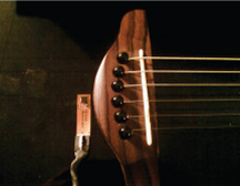
Figure 7: Accelerometer installed on Fender StratacousTIc guitar.
Using the accelerometer, built-in piezoelectric pickup and MEMS microphone each recorded a sound. Figure 8 shows the time-domain waveforms of each sensor. There is no post-processing of any segments.
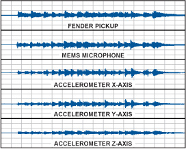
Figure 8: Time-domain waveforms using different sensors.
Fig. 9 shows the FFT spectrum of the piezoelectric pickup measured at a peak of the above-mentioned time-domain waveform. The results show that the response has a strong bass component. Indeed, there are many bass responses in actual audio files. This sound is more pleasing (also depends on personal preference), because cavity resonance can produce richer bass than directly heard from the instrument.
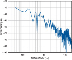
Figure 9: Spectrum of a piezoelectric pickup.
The output of the MEMS microphone is very flat, and the reproduction of musical sound is very good. The sound quality is very natural, well balanced, and high fidelity. The FFT spectrum measured at the same time as the piezoelectric pickup is shown in Fig. 10 (a). For reference, Figure 10 (b) shows the frequency response of the MEMS microphone.
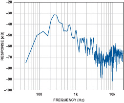
Figure 10 (a): Spectrum of MEMS microphone.
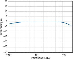
Figure 10 (b): Frequency response of MEMS microphone.
The output of the MEMS accelerometer is very interesting. The current shortcomings include the noise floor is too high, can be heard at the beginning and end of the audio track, and the Z-axis bandwidth is significantly limited to lower frequencies. The sound reproduction in each axis is also significantly different.
The sound on the X-axis and Y-axis is bright and clear, and there are obvious differences in tone. As expected, the sound on the Z axis is clearly mainly bass. Fig. 11 (a), (b) and (c) show the frequency spectra on the X, Y and Z axes respectively.
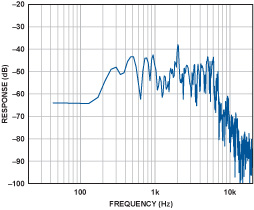
Figure 11 (a): Spectrum on the X axis.
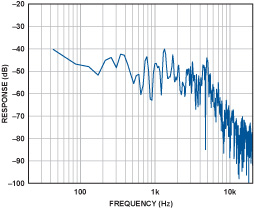
Figure 11 (b): Spectrum on the Y axis.
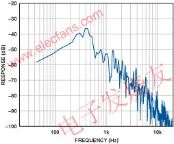
Figure 11 (c): Spectrum on the Z axis.
If the X, Y and Z axes are mixed together, a better reproduction of the musical sound can be achieved with a certain degree of clarity. By adjusting the mixing process, the tone balance can be changed to achieve natural music reproduction. Due to the current bandwidth limitation of the accelerometer, a larger range of high-frequency harmonics are lost, but the sound reproduction is still surprisingly realistic.
Conclusion
The low-g MEMS accelerometer does not have the traditional sound feedback problem, and can be used as a high-quality pickup for musical instruments, with obvious application potential. The above experimental results show that a 3-axis accelerometer attached to the Fender StratacousTIc guitar can achieve good musical reproduction. Because the vibration mode of the instrument body is different in different directions, the sound characteristics of the three axes of the accelerometer related to it are also different. Mixing the three channel outputs can reproduce the original sound effect. In addition, mixing the sound of these channels in different ways can produce creative sound effects.
In this experiment, although the application prospect is good from the performance of the accelerometer, there are some shortcomings, such as being able to hear the sensor's base noise, but the effect of this problem can be minimized by using noise gating or other techniques And the noise floor of an ideal sensor will be similar to that of a traditional microphone. The high-frequency response of the sensor needs to be expanded, ideally to reach 20kHz, so that it can cover the entire audio range of the instrument.
MEMS accelerometer technology has obvious potential advantages in the application of musical instruments, especially those field applications that are troubled by sound feedback problems. A very small, low-power MEMS device can be attached to any inconspicuous position in the instrument without affecting the natural vibration characteristics of the instrument. In fact, several sensors can be placed on different positions of the instrument to provide additional flexibility for acoustic engineers to reproduce the natural characteristics of the instrument without worrying about the sound feedback of the live application, so it can be said that the distance is "ideal music" Only one step away!
High Frequency PCB - Definition, Characteristics, Manufacturing, Materials and Application Scenarios
With the development of science and economy, the electronic industry has become an important driving force for economic development. Electronic products have become a part of life, affecting people's way of life. High-frequency circuit boards are widely used in many electronic industries and some instruments and equipment, and high-frequency PCB applications are also increasing. Choose high-frequency circuit board manufacturers in good service to buy high-quality products for use, we have to understand the relevant knowledge of high-frequency board.

What Is A High Frequency Circuit Board?
High frequency circuit board (HF PCB) is a special circuit board with high electromagnetic frequency. Generally speaking, high frequencies can be defined as frequencies above 1GHz. Its physical performance, accuracy and technical parameters are very demanding. It is often used in automobile anti-collision system, satellite system, radio system and other fields.
High Frequency PCB include:
- Rogers high frequency PCB
- Power amplifier high frequency PCB
- Buried blind hole mixed high frequency PCB
- Ceramic high frequency PCB
- Ceramic mixed high frequency PCB
- Communication antenna high frequency PCB
- GPS antenna high frequency PCB
- FR-4 high frequency PCB
- Double sided high frequency PCB
- Microwave High Frequency PCB
- Induction High Frequency PCB
- 2.4G Radar Induction PCB
- 5.8G Microwave Induction PCB

The utility model patented high frequency circuit board includes a core board with a hollow groove and a copper clad plate adhering to the surface and the lower surface of the core board by flow glue. The upper opening and the lower opening edges of the hollow groove are provided with a baffle.
The high frequency circuit board provided by the utility model is provided with a barrier which can block the flow glue at the upper and lower edges of the hollow groove of the core board.
In this way, the flow glue will not enter the hollow slot when the core plate is bonded with the copper clad laminate placed on the upper and lower surfaces, that is, the bonding operation can be completed by one press.
Compared with the existing technology, the high frequency circuit board can only be completed by secondary pressing. The high frequency circuit board in the utility model has the advantages of simple structure, low cost and easy manufacture.
Characteristics of High Frequency Circuit Board
Generally speaking, high frequency circuit boards have their own characteristics: low dielectric constant, relatively stable. In theory, the smaller the dielectric constant, the more stable the signal, and the higher the frequency circuit board can play a better role in signal transmission. Medium loss is very small, it is not easy to absorb water and moisture, heat resistance, corrosion resistance and other excellent performance. Conversely, if the dielectric constant is high, the signal transmission process is slow.
The thermal expansion coefficients of high frequency circuit boards and copper foil are also correlated to a certain extent. They are consistent as far as possible. The inconsistency can easily lead to the separation of copper foil in the alternate change of heat and cold. The later use will affect the signal transmission of PCB. The absorbency of high frequency circuit board is lower than that of other multi-layer circuit boards, because humidity will affect the dielectric constant and dielectric loss of high frequency circuit board. In addition, the heat resistance, chemical resistance, impact strength, peeling strength and other requirements are also good.
High frequency signals are vulnerable to noise and come with much tighter impedance tolerance as compared to conventional circuit boards.

High Frequency Circuit Board Materials
High frequency PCB have their own unique plates. Special materials are used to attain the high frequency given by the High Frequency PCB. PCB manufacturer commonly used Materials are: rogers(Rogers 4350B HF.Rogers RO3001.Rogers RO3003).Taconic(RF-35 Ceramic.TLX). Arlon(85N).Isola(IS620 E-fibre glass).F4B.TP-2.FR-4,Dielectric constant 2.2-10.6 and so on. FR4 is the cheapest one, while Teflon is the most expensive one. But they all have a common characteristic, which is the resin used in the material. The wiring of high frequency circuit board is exquisite and has great influence on components. High-frequency signals have the strongest impact on analog devices, so we should deal with the relationship between them to achieve the best performance. Therefore, high frequency is not easy to pass through high capacity electrolytic capacitors with poor high frequency performance.
The substrate material used in the high-frequency circuit board needs to have excellent electrical properties, good chemical stability, and the loss on the substrate is very small as the frequency of the power signal increases, so the importance of the high-frequency board is highlighted.
Therefore, when selecting a substrate for a PCB for a high-frequency circuit, it is particularly necessary to examine the various characteristics of the material DK at different frequencies. For the requirements of high-speed transmission of signal emphasis, or characteristic impedance control requirements, focus on DF and its performance under conditions of frequency, temperature and humidity.
Under the condition of frequency change, the general type of substrate material shows a large change of DK and DF values. Especially in the frequency range of l MHz to l GHz, their DK and DF values change more significantly. For example, a general-type epoxy resin-glass fiber-based substrate material (general type FR-4) has a DK value of 4.7 at a frequency of 1 MHz, and a DK value of 4.19 at a frequency of 1 GHz. Above lGHz, its DK value tends to be flat. The changing trend is smaller as the frequency increases (but the change is not large). For example, at 10 GHz, the DK value of FR-4 is generally 4.15, and the substrate material having high-speed and high-frequency characteristics changes in frequency. In the case of DK, the DK value changes little, and the DK keeps changing in the range of 0.02 from the frequency of change from 1 MHz to 1 GHz. Its DK value tends to decrease slightly from low to high frequency.
The dielectric loss factor (DF) of a general type of substrate material is affected by a change in frequency (especially in a high-frequency range), and the change in DF value is larger than that of DK. The law of change tends to increase. Therefore, when evaluating the high-frequency characteristics of substrate material, the focus of its investigation is on the change of its DF value. There are two distinct types of two types of substrate materials with high-speed and high-frequency characteristics. In general, there are two different types of substrate materials: one is that the (DF) value changes little with frequency. There is also a class that, although similar in magnitude to the general substrate material, has a lower (DF) value.
High-frequency circuit boards with induction heating technology have been widely used in the communication industry, network technology field promotion and high-speed information processing systems to meet the requirements of many high-precision parameter instruments. A reliable high-frequency circuit board provides great help in actual production.
From material DF:
The circuit board material with DF between 0.01 and 0.005 is suitable for the digital circuit with the upper limit of 10Gb / S;
DF between 0.005-0.003 is suitable for digital circuits with an upper limit of 25gb / s;
Circuit board materials with DF no more than 0.0015 are suitable for 50GB / s or even higher speed digital circuits.
Common high-speed PCB materials are:
1) Rogers: ro4003, ro3003, ro4350, ro5880, etc
2) TUC: tuc862, 872slk, 883, 933, etc
3) Panasonic:Megtron4.Megtron6, etc
4) Isola: fr408hr, is620, is680, etc
5) Nelco:N4000-13.N4000-13EPSI, etc
6) ShengYi
Of course, there are many other high-frequency board materials, such as Arlon (acquired by Rogers) and Taconic, which are all old brand RF microwave material factories with guaranteed performance.
Our most common request is for FR-4 material, which is composed of woven fiberglass bound by an epoxy resin, and which we always keep stocked as one of our PCB Options at a Standard Price. FR-4 is a robust material with excellent thermal characteristics, and electrically it is known to perform quite reasonably at RF or Microwave frequency levels.
Some clients whose designs are intended for particularly demanding applications-such as high-power or broadband circuits-find that FR-4 sometimes just does not do the job at those higher frequencies. In these cases, we are always happy to help you find a laminate material to suit your specific needs, and our highly customizable PCB Assembly Process can be easily adjusted to make sure your project lead time is not impacted.
A snapshot of the datasheet for FR-4 material is shown below for reference.

The most popular high-frequency-specific laminate materials were developed by Rogers, and referred to with an [RO-[ prefix. These high-quality materials exhibit approximately a 20% reduction in dielectric constant, compared to standard FR-4; they also boast rather impressive thermal characteristics, with Tg values above 280°C . A snapshot of the datasheet for RO4350B and RO4003C is included below for your convenience.

Requirements for Manufacturing Materials of High Frequency PCB
1. Dielectric loss (Df) must be small, which mainly affects the quality of signal transmission. The smaller the dielectric loss, the smaller the signal loss.
2. Low water absorption. High water absorption will affect dielectric constant and dielectric loss when damped.
3. The dielectric constant (DK) must be small and stable. Usually the smaller the better. The transmission rate of the signal is inversely proportional to the square root of the dielectric constant of the material. High dielectric constant easily causes signal transmission delay.
4. The coefficient of thermal expansion of copper foil is the same as that of copper foil, because the inconsistency will cause the separation of copper foil in the change of cold and heat.
5. Other heat resistance, chemical resistance, impact strength and peeling strength must also be good.
Generally speaking, high frequency can be defined as frequency above 1 GHz. At present, most of the high frequencies used are fluorine dielectric substrates. Teflon is much better than other substrates, such as PTFE, which is usually called Teflon. However, Teflon substrate has the disadvantage of high cost and large heat resisting property..
How to choose high frequency high speed PCB material
To select the PCB substrate, a balance must be made among meeting the design requirements, mass production and cost. In short, the design requirements include electrical and structural reliability. Generally, when designing a very high-speed PCB Board (frequency greater than GHz), PCB material problem will be more important. For example, the FR-4 material, which is commonly used now, has a large dielectric loss DF (dielectric loss) at several GHz, which may not be applicable.
For example, 10Gb / s high-speed digital signal is a square wave, which can be regarded as the superposition of sine wave signals of different frequencies. Therefore, 10Gb / s contains many different frequency signals: 5GHz fundamental signal, 3-order 15GHz, 5-order 25ghz, 7-order 35GHz signal, etc. The integrity of the digital signal and the steepness of the upper and lower edge are the same as the low loss and low distortion transmission of the RF microwave (the high-frequency harmonic part of the digital signal reaches the microwave frequency band). Therefore, in many aspects, the selection of high-speed digital circuit materials is similar to the requirements of RF microwave circuits.
The main factors to be considered in the selection of suitable base materials are as follows:
1. Manufacturability:
2. Various performances (electrical, performance stability, etc.) matching with products:
Low loss, stable Dk/Df parameters, low dispersion, small variation coefficient with frequency and environment, small tolerance of material thickness and glue content (good impedance control), if the trace is long, consider low roughness copper foil. In addition, the high-speed circuit needs to be simulated in the early stage of design, and the simulation result is the reference standard of the design. "Xingsen Technology-Agilent (High Speed/RF) Joint Lab" solves the performance problems of inconsistent simulation results and tests. It has done a lot of simulation and actual test closed-loop verification, and the simulation can be consistent with the actual measurement through unique methods.
3. The availability of materials in a timely manner:
Many high-frequency board material procurement cycles are very long, even 2-3 months; in addition to the conventional high-frequency board material RO4350 in stock, many high-frequency boards material need to be provided by customers. Therefore, high-frequency plates need to communicate with manufacturers in advance, and prepare materials as soon as possible;
4. Cost:
5. Applicability of laws and regulations:
It should be integrated with environmental protection regulations of different countries to meet the requirements of RoHS and halogen-free.
Among the above factors, the high-speed digital circuit operation speed is the main factor to be considered in PCB material selection. The higher the speed of the circuit, the smaller the DF value of the selected PCB material. The low loss circuit board will be suitable for 10Gb / s digital circuit; 25gb / s digital circuit needs to select the board with lower loss; ultra-low loss board will be suitable for the faster high-speed digital circuits, and its speed can be 50GB / s or higher.
How to Make High Frequency Circuit Board?

Fabrication Principle of High Frequency Circuit Board
In the design of high frequency circuit, the power supply is designed in the form of layers, which is much better than that in the form of buses in most cases, so that the circuit can always follow the path with the smallest impedance. In addition, the power board has to provide a signal loop for all generated and received signals on PCB, which can minimize the signal loop and reduce noise, which is often ignored by low frequency circuit designers.
In the design of high frequency PCB, we should follow the following principles:
- Unity of power supply and ground, stability.
- Careful wiring and proper termination can eliminate reflection.
- Careful consideration of wiring and proper termination can reduce capacitive and inductive crosstalk.
- Noise suppression is needed to meet EMC requirements.
Points for Attention in Manufacturing High Frequency Circuit Board
1. Impedance control is strict, relative line width control is very strict, general tolerance is about 2%.
2. Because of the special plate, the adhesion of PTH copper deposit is not high. Usually, plasma treatment equipment is needed to roughen the through-hole and surface to increase the adhesion of PTH copper and solder resist ink.
3. Do not grind the plate before welding resistance, otherwise the adhesion will be very poor, and can only be coarsened with micro-corrosive powder.
4. Most of the sheets are PTFE materials. There will be many rough edges when they are formed by ordinary milling cutters, which need special milling cutters.
5. High frequency circuit board is a special circuit board with high electromagnetic frequency. Generally speaking, high frequency can be defined as frequency above 1 GHz.
Its physical performance, accuracy and technical parameters are very demanding. It is often used in automobile anti-collision system, satellite system, radio system and other fields.
Scenario and Field of High Frequency Circuit Board Application:
- Communication Base Station
- Repeater
- GPS antenna
- Radio Frequency Antenna
- power amplifier
- Signal amplifier
- Wave filter
- coupler
- attenuator
- Power divider
- 3DB Bridge, etc.
Nowadays, the high frequency of electronic equipment has become a trend of development, especially in the growing development of communication networks, aerospace, military equipment, intelligent transportation, information products are also increasingly high-speed and high-frequency. Nowadays, with the development of science and economy, many new products need high frequency circuit boards. High frequency circuit boards play an increasingly important role in people's daily life.
It is not easy to find a fast and good manufacturer of high frequency circuit boards. Jinghongyi PCB has its own unique board advantages in making high frequency circuit boards. It has reliable automatic production equipment and testing equipment.
Reasons for Choosing Jinghongyi PCB
1. Top imported raw materials for high frequency circuit boards to ensure product quality from the source
- Plate: Shengyi, South Asia, KB.Rogers.Taconic. Isola. Arlon.F4BM.Nelco.Hitachi.
- Potions: Rohm&Haas (US) Atotech (Germany) Umicore (Germany)
- Ink: Taiyo (Japan)
- Dry membrane: Asahi (Japan), Dupont (US)
2. Full set of surface treatment equipment to meet the needs of various industries
We are one of the few companies in PCB industry equipped with complete surface treatment equipment.We can deal with the Immersion Gold completely.
Immersion Silver, Immersion tin, OSP, tin spraying, gold plating, thick gold plating, tin plating, silver plating and other related requirements.
3. Leading PCB Multilayer Circuit Board Technology Capability
- Maximum Layer: 28 layer
- Maximum Plate Thickness: 6.0mm
- Maximum Thickness to Diameter Ratio 10:1
- Maximum Copper Thickness: 6OZ
- Maximum working plate size: 1000x610mm
- Thinnest 4 Layer PCB : 0.33mm
- Minimum mechanical hole/pad: 0.2/0.40mm
- Drilling accuracy: +/-0.05mm
- PTH Aperture Tolerance: +/-0.05mm
- Minimum Linewidth/Line Spacing: 3mil/0.075mm
4. Strict PCB quality control system to effectively guarantee product performance
- Strictly control according to IPC standard to ensure 100% qualified rate of shipment quality.
- Implement quality PDCA cycle process to continuously improve product performance
- Imported DIONEXICS-900 and Temperature Cycle Inspection Equipment from USA to ensure high reliability and stability of products
5. Top Technical Team
Eight years of focus on R&D and manufacture of high-frequency board and microwave radar RF circuit board, with a dedicated, united and tenacious R&D team, customers NPI stage products, all into the process evaluation system, meet the evaluation criteria of the project, further review by the R&D team and file a case tracking the whole process.
The staff has 3-12 years of professional and technical personnel with multi-layer circuit board experience. They have rich experience in various industry standards and process quality requirements.
6. Intimate service
Service concept: regard customers as eternal partners, develop together, only choose reputation, not customers, regardless of the size of customers, in the case of customer needs, to provide the best service.
Flexible service: We will be eager to meet the customers'needs, think what they want, and do our best to help customers solve problems, reduce losses or promote project development.
Useful Resources
- Ten PCB Routing Rules for High Frequency Circuits
- Difference between High Frequency Circuit and High Speed Circuit
- Interference Analysis and Countermeasure in High-Frequency PCB Design
High Frequency PCB
High Frequency PCB, High Frequency Circuit Board, High Frequency PCB Design, High Frequency PCB Materials
JingHongYi PCB (HK) Co., Limited , https://www.pcbjhy.com