introduction
8 b / 10 b is the encoding mechanism currently used in many high-speed serial buses, such as USB 3.0, 1394b, Serial ATA, PCI Express, Infini-band, Fiber Channel, RapidIO and other buses or networks. The 8 b / 10 b coding method was originally invented by IBM in 1983 and applied to ESCON (200M Interconnect System), and published "Research and Development" of Al Widmet and Peter Franaszek IBM publications. The 8 b / 10 b codec can be widely used, mainly due to the following advantages: the use of an embedded clock, which can maintain DC balance; can more effectively detect errors; isolate data symbols and control symbols.
In order to realize 8 b / 10 b encoding and decoding of data in USB 3.0, the method of combining lookup table method and combinational logic is adopted to decompose 8b / 10b encoding and decoding into 5 b / 6 b encoding and decoding and 3 b / 4 b Encoding and decoding, using Verilog HDL language to achieve the description of the algorithm, and passed Modelsim simulation, and then implemented a specific hardware circuit on FPGA. Using a 500 MHz clock signal, the test meets the USB 3.0 transmission rate of 5 Gb / s. This innovative method uses a small amount of logic, implements the 8 b / 10 b codec, and meets the requirements of USB 3.0 high-speed data transmission.
1 Principle of 8 b / 10 b codec in USB 3.0
In the USB 3.0 layered structure, the sending end first scrambles the data or control word (K), and then encodes the scrambled 8 b data into 10 b; the receiving end first decodes the received 10 b data to get 8 b data, and then descramble it to get the original data.
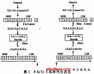
8 b / 10 b encoding includes encoding of 256 data characters and 12 control characters. Data characters and control characters are represented by Dx, y and Kx, y respectively, where x represents the decimal value corresponding to the lower 5 bits of 8 b (EDCBA); y represents the decimal value corresponding to the upper 3 bits of 8 b (HGF) . When encoding, the transmitting end changes the lower 5 bits into 6 bits and the upper 3 bits into 4 bits according to the encoding table. After the encoding is completed, the 10 b parallel characters are converted into serial and sent out. During decoding, the receiver first performs serial-to-parallel conversion to obtain the 10 b character, and then decomposes the character into 6 b and 4 b. According to the corresponding coding table, it is valid and finally completes the decoding. The codec conversion process is shown in Figure 1.
The unbalance degree disp (disparity) represents the difference between the number of "1" and the number of "0" in one codeword after encoding. "1" is represented by +1, "0" is represented by -1, and the sum of all "+1" and "-1" in the codeword is disp. 8 b / 10 b coded disp takes 3 states: "+2" (6 1s and 4 0s), "0" (5 0s and 5 1s), "-2" (6 0s and 4s) 1). The running inconsistency RD (Running Disparity) is a binary parameter with only two states, positive and negative, used for coding mode control. In the 8 b / 10 b coding table, the 10 b characters are divided into two types of code tables (RD- and RD +). During the encoding process, the corresponding code table is selected by judging whether the RD value is positive or negative. If the current RD is negative (RD-), the encoder will select the corresponding value output in the RD-coding table and detect the corresponding output 10 b value Disp, if disp = 0, RD remains unchanged RD-, otherwise RD value becomes RD +; if the current RD is positive (RD +), then select the corresponding value output in the RD + coding table, and detect the disp corresponding to the output value , If disp = 0, RD remains unchanged RD +, otherwise RD becomes negative RD-. In short, when disp is positive or negative, RD alternately transforms. This method is to make the distribution of 0 and 1 more uniform and reduce the DC component of the differential signal.
2 Design of 8 b / 10 b encoder
The 8b / 10b encoder splits the 8 b data input into lower 5 bits and upper 3 bits to encode 5 b / 6 b and 3 b / 4 b respectively, and performs encoding according to the encoding table. Because of some special 3b / 4 b encoding, a special 3 b / 4 b encoding module is needed. The encoded data is selected and output by the RD control module, and the RD status at this time is fed back to the next round of encoding. For 8 b control input, since only 12 kinds of K control codes are valid, an identification module for invalid K codes is needed. Therefore, the encoder is divided into 5 modules: 5 b / 6 b encoding, 3 b / 4 b encoding, special 3 b / 4 b encoding, invalid K code detection, RD_controller, the first 4 parts are parallelized under the control of RD_controller Encoding, as shown in Figure 2. In the figure, kin is 8 b control input, and data_in is 8 b data input. Since the USB 3.0 transmission speed is 5 Gb / s, the encoder clk is 500 MHz.
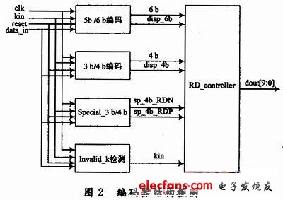
5 b / 6 b encoding module, 3 b / 4 b encoding module divide the input 8 b data input into lower 5 bits and higher 3 bits for parallel encoding, output 6 b and 4 b data constitute 10 b encoding, and output disp_6b , Disp_4b is the imbalance of 6 b and 4 b data.
In the 8 b / 10 b conversion table, the upper 3 bits of the 8 b data input are "111", and the lower five bits are "01011", "01101", "01110", "10001", "10010", "10100" ", The output 4 b is a special case, the special 3 b / 4 b encoding module is to complete the output of these special cases, and the output sp_4b_RDN and sp_4b_RDP are the unbalance of the special encoding.
When the 8 b input is a control K code, only 12 types of control codes are valid. The invalid K code detection module is to detect whether the input control code is valid. If invalid, output invalid_k = 1, if valid, invalid_k = 0.
In addition to selecting and outputting the encoded data, the RD control module mainly follows the new current RD value according to disp_6b, disp_4b, sp_4b_RDN and sp_4b_RDP, and feeds back to the next round of encoded RD input to maintain the DC balance of differential signal transmission.
Down Tube Battery,Ebike Lithium Battery,24V Bottle Battery,24V Electric Bicycle Battery
Changxing Deli Technology Co., Ltd. , https://www.delipowers.com