Stepper motors are generally divided into three types: permanent magnet (PM), reactive (VR) and hybrid (HB). Currently, two-phase hybrid stepper motors are the most widely used. This design uses a two-phase four-wire stepper motor with a step angle of 1.8 ° without subdivision. The basic principle of the stepping motor is in communication with the ordinary permanent magnet synchronous motor. It is an open-loop control element that converts the electrical pulse signal into angular displacement or linear displacement. In the case of non-overload, the speed and stop position of the motor only depend on the frequency and pulse number of the pulse signal, and are not affected by the load change. That is, a pulse signal is added to the motor, and the motor rotates by a step angle. The drive circuit of the stepper motor works according to the control signal generated by the single chip microcomputer. The internal structure of the two-phase stepper motor is shown in Figure 1.
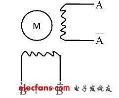
Figure 1 Internal structure of two-phase stepper motor
It can be seen from FIG. 1 that the stepping motor has A and B two-phase windings, due to the particularity of the induction sub-stepping motor. When a symmetrical positive-rotating alternating current is passed through the two-phase windings of A and B, a circular rotating magnetic field will be generated.
The order is to pass the windings in order to determine the magnitude of the direct current, which will produce a 4-step one-cycle stepping rotating stator magnetic field with a step angle of 90 °. In order to make full use of the capacity of the motor. To increase the output force distance, the two-phase stepper motor is usually used for the whole step operation
Power-on sequence. At this time, the stepper motor rotates forward, and when the energization sequence reverses, the stepper motor reverses.
Zener Diode, the English name Zener diode, also known as Zener diode. By using the reverse breakdown state of the pn junction, the current can be varied over a wide range and the voltage is substantially constant, and the diode that acts as a voltage regulator is fabricated. [1] This diode is a semiconductor device that has a very high resistance until the critical reverse breakdown voltage. At this critical breakdown point, the reverse resistance is reduced to a small value in this low resistance region. The current is increased and the voltage is kept constant. The Zener diode is binned according to the breakdown voltage. Because of this characteristic, the Zener diode is mainly used as a voltage regulator or voltage reference component. Zener diodes can be connected in series for use at higher voltages, resulting in higher regulated voltages in series.
Zener Diode
Power Zener Diode,Zener Diode,Zener Diode Regulator,Zener Diode 56V
Dongguan Agertech Technology Co., Ltd. , https://www.agertechcomponents.com