At the 2011 IIC-China, PI demonstrated two zero standby power solutions, one based on its integrated off-line switch IC - LinkZero-AX's zero standby power solution, which attracted many design engineers. We all know that when the electronic products are in standby, the main power supply is not working, and the auxiliary power supply is in working state. PI's LinkZero-AX adopts a new power-off mode, which can effectively turn off the auxiliary power supply when the power supply is unloaded. . The power-down mode is triggered by a signal acquired by the microcontroller, which completely shuts down the switching operation and the internal switch control circuitry, thereby eliminating the energy wasted by these unwanted functions. In power-down mode, LinkZero-AX does not terminate the operation, and the IC can be woken up by a reset pulse or a button press.
"In fact, the zero standby power consumption proposed here is not completely zero standby power consumption, but the standby power consumption is reduced to a very low level. Generally, the standby power consumption of 10 milliwatts can be measured, but below 10 milliwatts, the measurement is very good. Difficult, so it can be called zero power!†said Doug Bailey, vice president of marketing at Power Integrations. Actual measurements show that LinkZero-AX can reduce the standby power consumption of high-power consumer products and appliances to 4 mW or even close to zero watts. (According to Clause 4.5 of IEC 62301, standby power below 5 mW is considered zero power.)
As energy conservation and environmental protection have become the consensus, lower standby power consumption technology has also received attention from consumers. It is understood that the electrical energy consumed by electrical products during standby has become a serious waste of energy. According to a survey conducted by the China Energy Conservation Product Certification Center, there are nearly 10 kinds of household appliances with standby functions in an urban household. The average standby power consumption per month is between 15-30 watts, which accounts for about 10% of household electricity consumption. . In other words, 10% of the electricity bill you pay each month is to pay for standby, so energy-saving technology has the potential to dig deep.
"Another standby phenomenon is the charger. For example, after the mobile phone charger is fully charged, many users do not power off in time, causing the charger to continue to consume current in the standby state." Doug stressed, "after adopting our solution, This phenomenon can be eliminated.†For this zero standby requirement, PI introduced the LinkZero-LP product, which is suitable for chargers and adapters. LinkZero-LP uses a new control technology that allows the device to automatically enter no-load mode and can be woken up from no-load mode, while no-load power consumption is 4 mW - which is much lower than the zero no-load power consumption specified by the IEC standard.
“LinkZero-LP can automatically monitor the load, enter the power-down mode when the load is removed, and automatically re-activate after the load is applied again.†Doug pointed out, “In addition, the IC power supply during startup and operation comes directly from the drain pin, no need Use the startup circuit. The jitter of the internal oscillation frequency greatly reduces the quasi-peak and average EMI, which reduces the filter cost."
Currently, PI provides a low-power zero-standby solution, as shown in the following figure. 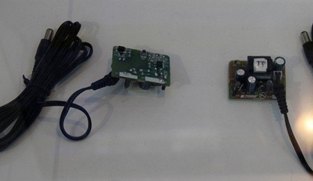
Figure 1 PI 2.1W CC/CV charger solution, based on PI LinkZero-LP device, standby power consumption is close to 0 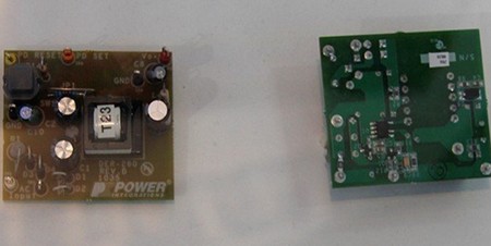
Figure 2 PI 1.5W non-isolated flyback power supply, standby power consumption is close to 0
Doug revealed that PI will develop zero standby power products from two directions in the future, one direction is to further reduce standby power consumption, to the true "zero power consumption" development, and the other direction is to expand the product application field to higher power products. For example, white goods, large electrical equipment, and so on. Due to the increasing popularity of flat-panel digital TVs, it takes time to boot up, and many users already know that the damage caused by the startup transient current is very large, so many Chinese users no longer use the direct power-off mode used in the CRT TV era, but let The appliance is in a standby state, and such a habit is in urgent need of a zero standby power consumption product.
Now, in addition to PI, Fairchild Semiconductor, NXP and other companies have begun to introduce zero standby power products. I believe that in the near future, zero standby power consumption will usher in the era of popularization.
Background knowledge: Analysis of standby power consumption mechanism of switching power supply
At present, most electronic devices below 100W, such as power adapters, chargers, cordless phones, ADSL routers, LCD monitors and DVDs, use off-line flyback switching circuits to convert 85V to 275V AC provided by the grid into The DC voltage required for electronic equipment. Under normal operating conditions, the losses of the flyback switching power supply mainly include conduction loss and switching loss, as well as loss of the control circuit. In the standby state, since the output current of the system is close to zero, the conduction loss can be neglected, and the switching loss and the loss of the control circuit become the main system standby power consumption. To reduce standby power consumption, attention should be paid to switching losses and loss of control circuitry. 
The figure above shows the main loss types of the flyback switching power supply in standby mode. The power tube switching loss, drive loss, transformer core loss, output rectifier reverse recovery loss and buffer loss are all switching losses. Various types of switching losses are related to the switching frequency, and reducing the switching frequency can reduce switching losses. The loss of the control circuit is mainly represented by the loss on the starting resistor, and the loss of the starting resistor is directly related to the rectified DC bus voltage and the starting resistor value. The startup resistance loss can be reduced by reducing the startup current under operating conditions that guarantee a wide voltage input.
This article refers to the address: http://
2)High speed custom labeling and printing on flanges available – even on short runs
3)One piece molded construction for strength and precision
4)Appealing designs as well as ergonomics (no sharp edges)
| Type |
Weight (g) |
d1 (mm) |
D1 (mm) |
d2 (mm) |
D2 (mm) |
H1 (mm) |
H2 (mm) |
d3 (mm) |
A1 (mm) |
A2 (mm) |
d4 (mm) |
E (mm) |
| DIN-125 | 170 | 125 | 80 | 100 | 125 | 20 | 12.5 | 12.5 | 7 | 20 | ||
| DIN-160 | 350 | 160 | 100 | 128 | 160 | 22 | 16 | 16 | 13 | 32 | ||
| DIN-200A | 600 | 200 | 125 | 160 | 200 | 22 | 20 | 20 | 13.5 | 32 | ||
| DIN-200B | 600 | 200 | 125 | 160 | 200 | 32 | 20 | 20 | 13.5 | 32 | ||
| DIN-200C | 650 | 200 | 125 | 160 | 200 | 32 | 20 | 20 |
|
|
||
| DIN-250A | 1050/1200 | 250 | 160 | 160 | 200 | 22 | 20 | 20 | 13 | 32 | ||
| DIN-250B | 1050 | 250 | 160 | 160 | 200 | 32 | 20 | 20 | 13 | 32 | ||
| S-250 | 1230 | 250 | 160 | 157 | 197 | 127 | 20 | 20 |
|
|
||
| NP-13A | 885 | 202 | 119 | 154 | 188 | 32 | 17 | 17 | 9/14 | 49/26.75 | ||
| NP-13B | 885 | 202 | 119 | 154 | 188 | 33 | 17 | 17 | 9.5/12.5 | 50.25/26.25 | ||
| NS-4 | 225 | 120 | 75 | 130 | 150 | 16/20 | 10 | 10 | 10 | 22 | ||
| NS-5A | 220 | 120 | 54 | 130 | 150 | 16/20 | 10 | 10 |
|
|
||
| NS-5B | 220 | 120 | 54 | 130 | 150 | 22 | 10 | 10 |
|
|
||
| LH-120 | 170 | 120 | 50 | 100 | 120 | 16/20 | 10 | 10 | 6 | 17 | ||

ABS Wire Spool, Plastic Spools, Plastic Spools For Wire, Plastic Spool Bobbin
NINGBO BEILUN TIAOYUE MACHINE CO., LTD. , https://www.spool-manufacturer.com