What is SOC?
In the mid-1990s, inspired by the use of ASICs to implement chipsets, it was the idea of ​​integrating all the different functional blocks of a complete computer directly into a single piece of silicon at a time. This chip, originally called System on a Chip (SoC), literally translated Chinese name is a system-on-chip.
How to define the SoC, the understanding is not unified. But can be summarized as follows:
1SoC should be composed of IP cores that can be designed and reused. IP cores are VLSI blocks that can be sold separately with complex system functions;
2IP core should adopt deep sub-micron process technology;
There may be multiple MPUs, DSPs, MCUs or their composite IP cores in the 3SoC.
SoC technology design system chip process
Designing system chips with SoC technology generally involves software and hardware partitioning. The design is basically divided into two parts: chip hardware design and software collaborative design. The chip hardware design includes:
1. Functional design phase.
For the application of the designer's products, set some specifications such as function, operating speed, interface specification, ambient temperature and power consumption as the basis for future circuit design. It is further possible to plan how the software modules and hardware modules are divided, which functions should be integrated in the SOC, and which functions can be designed on the circuit board.
2. Design description and behavioral level verification
Once the design is complete, the SOC can be divided into functional modules based on functionality and the IP cores that will be used to implement these functions are determined. This phase will affect the internal architecture of the SOC and the inter-modules
Dynamic signals and the reliability of future products. Once the module is decided, the design of each module can be implemented in a hardware description language such as VHDL or Verilog. Next, use VHDL or Verilog's circuit simulator to perform functional verification of the design (funcTIonsimulaTIon, or behavioral verification simulaTIon). Note that this functional simulation does not take into account the actual delay of the circuit, but does not yield accurate results.
3. Logical synthesis
Once the design description is correct, it can be synthesized using a synthesizer. In the synthesis process, it is necessary to select an appropriate logic cell library as a reference for synthesizing logic circuits. The programming style of the hardware language design description file is an important factor in determining the efficiency of the synthesis Tool. In fact, the HDL grammar supported by the synthesis tool is limited. Some overly abstract grammars are only suitable for the simulation model when evaluating the system, but cannot be accepted by the synthesis tool. The logic synthesis gets the gate level netlist.
4. Gate-Level Netlist VerificaTIon
Gate level functional verification is register transfer level verification. The main job is to verify that the integrated circuit meets the functional requirements, which is typically done using gate level verification tools. Note that this stage of the simulation needs to consider the delay of the gate.
5. Layout and routing
Layout means that the designed function modules are reasonably arranged on the chip and their positions are planned. Wiring refers to the wiring that completes the interconnection between modules. Note that the connections between modules are usually long, so the resulting delay can seriously affect the performance of the SOC, especially above the 0.25 micron process, which is even more pronounced.
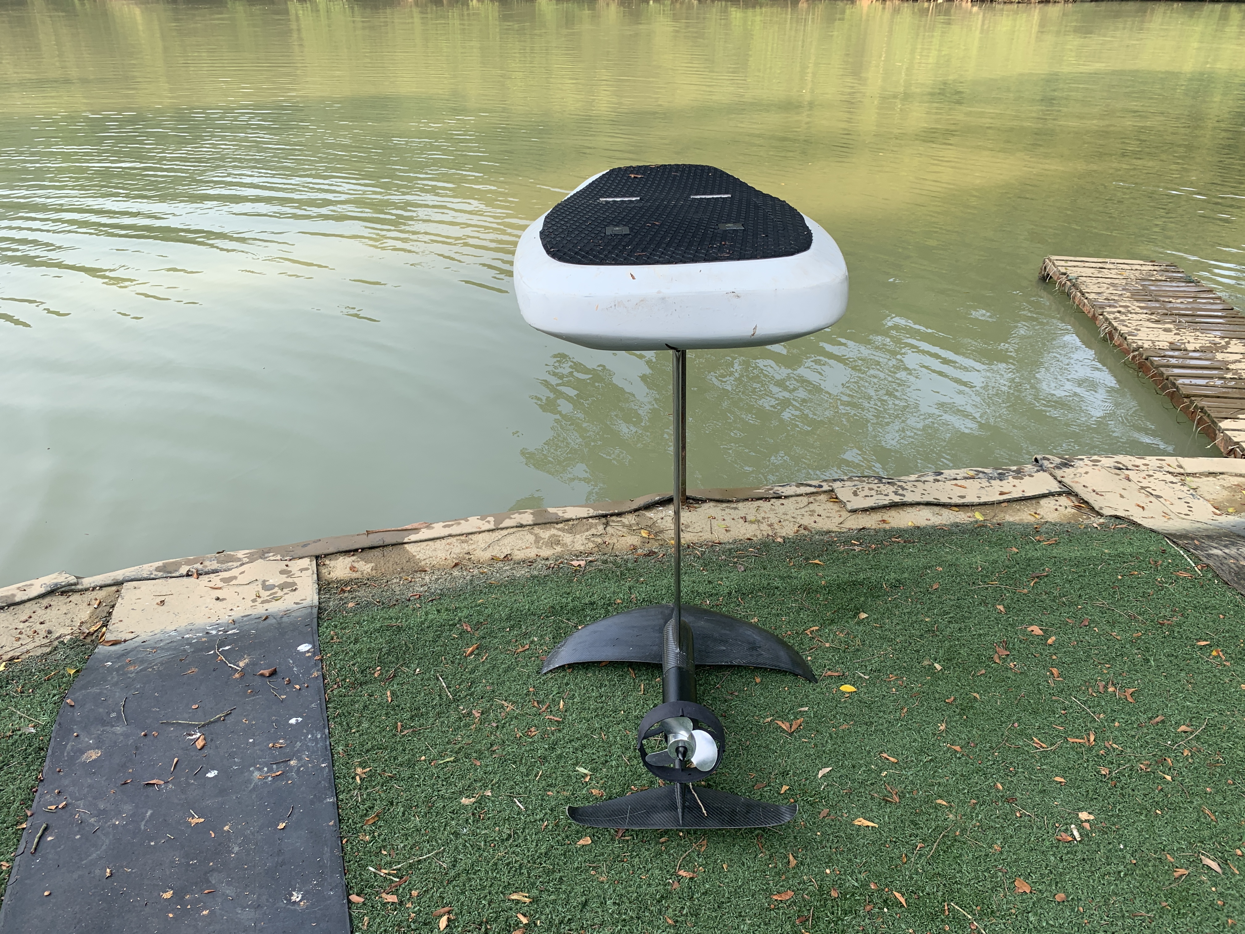
Electric Hydrofoil Propulsion System is a powerful Underwater Jet System, Application to hydrofoil , surfboard,small fishing boats ,Even you can use it for diving booster. Our Electric hyrdofoil propulsion system is a Tunnel Jet type propulsion system. With the protective shield on both side, these type design can keep the propeller safe ,avoid Accidental inhalation of the grass, fishes. High efficiency brushless motor with the propeller get the lower working current and long continuouse working time. This is quite different of our proulsion system to compare with other oridinary tunnel jet systems. We use the boat ESC as the controller ,and it is only 150A , we controled our tunnel jet engin working with lowercurrent .reduce the cost and improve the system life. economy for maintenance and repair.The system shell made by Aluminium Alloy 6061,light weight, small size but powerfull thrust.

Electric Hydrofoil Propulsion System
Underwater Jet System,Electric Tunnel Thruster,Electric Underwater Boat Propulsion System
shenzhen GC Electronics Co.,Ltd. , https://www.jmrdrone.com