Inverter working principle
Saturday, January 09, 2010 15:36 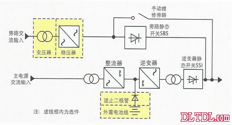
The inverter can be applied to the UPS power supply, the battery is charged to the battery discharge, and the direct current is converted to alternating current through the inverter to supply power to the load.
ACDC is realized by a rectifying circuit. Generally, the commonly used rectifying circuit has three types: full bridge, half bridge, and half wave rectification. The core component of the circuit is a diode.
DCAC converts direct current into alternating current. The inverter is usually implemented by a push-pull circuit. The input DC is twisted into two alternating currents in two directions, and then output through the push-pull transformer. The coil can get AC power.
We know that DC power cannot be directly boosted and the AC current can pass through the coil turns. The turns ratio is the operating principle of the inverter:
1. DC power can be changed to AC by oscillating circuit
2. The obtained AC power is boosted by the coil (the square wave AC is obtained at this time)
3. Rectifying the obtained alternating current to obtain a sine wave
AC-DC is relatively simple. We know that diodes have unidirectional conductivity. This characteristic of diodes can be used to connect a bridge so that one end is always inflow and the other end is always flowing out. This gives a voltage sinusoidal change of DC if needed. Smooth DC power also needs to be rectified simply by connecting a capacitor
-------------------------------------------------- -------------------------------------------------- -------------------------------
The inverter Inverter is a DC to AC transformer, which is actually a voltage inversion process with the Adapter. The Adapter converts the AC voltage of the mains grid into a stable 12V DC output, while the Inverter converts the 12V DC voltage output by the Adapter into a high-frequency AC high-voltage AC; both parts also use the pulse width that is currently used more. Modulation (PWM) technology. The core part is a PWM integrated controller, Adapter is UC3842, I
Nverter uses the TL5001 chip. The TL5001 operates from a voltage range of 3.6 to 40V and features an error amplifier, a regulator, an oscillator, a PWM generator with dead-band control, a low-voltage protection loop, and a short-circuit protection loop.
The following is a brief introduction to the working principle of Inverter: 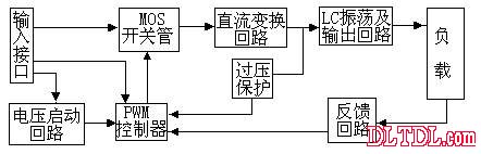
Inverter working principle block diagram input interface part:
The input section has 3 signals, 12V DC input VIN, working enable voltage ENB and Panel current control signal DIM. VIN is provided by the Adapter. The ENB voltage is provided by the MCU on the motherboard. The value is 0 or 3V. When ENB=0, the Inverter does not work, and when ENB=3V, the Inverter is in normal working condition; and the DIM voltage is provided by the motherboard. The range of variation is between 0 and 5V. The different DIM values ​​are fed back to the feedback terminal of the PWM controller. The current supplied by the Inverter to the load will also be different. The smaller the DIM value, the larger the current output by the Inverter.
Voltage start circuit:
When ENB is high, the high voltage is output to illuminate the backlight tube of the panel.
PWM controller:
There are several functions: internal reference voltage, error amplifier, oscillator and PWM, overvoltage protection, undervoltage protection, short circuit protection, and output transistors.
DC conversion:
The MOS switch tube and the energy storage inductor form a voltage conversion circuit, and the input pulse is amplified by a push-pull amplifier to drive the MOS tube to perform a switching action, so that the DC voltage charges and discharges the inductor, so that the other end of the inductor can obtain an AC voltage.
LC oscillation and output loop:
Ensure that the lamp starts at the required 1600V voltage and reduce the voltage to 800V after the lamp is turned on.
Output voltage feedback:
When the load is working, the sampled voltage is fed back to stabilize the Inventer voltage output.
For industrial control environment wired communication equipment and wireless communication equipment. Wired communication equipment mainly introduces serial equipment communication for industrial field, professional bus-type communication, industrial Ethernet communication and conversion equipment between various communication protocols, including routers, switches, modems and other equipment. Wireless communication equipment mainly includes wireless AP, wireless bridge, wireless network card, wireless lightning arrester, antenna and other equipment. Communications also include military communications and civilian communications
Communication Pcb,Wireless Communication Pcb,Optical Communication Circuit Board,Printed Communication Circuit Boards
Chuangying Electronics Co.,Ltd , https://www.cwpcbs.com