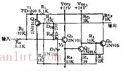
Schmitt variable hysteresis flip-flop circuit
The figure shows the trigger circuit diagram of Schmitt variable hysteresis. Q1 and Q2 in the circuit are typical Schmitt circuits. Q2 acts as a buffer stage and therefore does not load the drive circuit. In the normal case, Q1 is turned off and Q2 is turned on, and the voltage Va is approximately Va=R8*Vin/R0+R8. The above situation assumes that there is no Zener D8 or Q3 load on R8 and Q2 is low. Because Q4 is off, D1 is reverse biased, so R7 is not in the circuit, that is, R7 is removed from the circuit.
When Va approaches the circuit's inherent upper trigger level X, Q1 begins to conduct until Q2 turns off, which in turn turns on Q4. Now D2 is reverse biased, so R4 is removed from the circuit. D1 becomes forward biased, putting R7 into operation. So Va=R7*Vin/R0+R7. In this way, the lower trigger point can be controlled with R7. A Zener diode is used to limit the maximum voltage of R0 and prevent Q1 from becoming a forward bias.
French type cable reel Non-rewirable, 230V~, IP20, Class I, with a thermal cut-out, with a non-rewirable plug with cord H05VV-F 3G1,0-1,5mm 2 ,
with 4-way socket outlet with or without shutters.
French Cable Reel,Electric Cord Reel,Cable Drum,Cable Drum Roller
CIXI KYFEN ELECTRONICS CO.,LTD, , https://www.kyfengroup.com