First, before diving into the theme, it's essential to understand some fundamental knowledge about STM32 series chips and their models:
The startup files for different STM32 series include: startup_stm32f10x_cl.s for interconnected devices like STM32F105xx and STM32F107xx; startup_stm32f10x_hd.s for large capacity STM32F101xx, STM32F102xx, and STM32F100xx; startup_stm32f10x_ld.s for small capacity STM32F103xx; startup_stm32f10x_hd_vl.s for small-capacity large-capacity STM32F101xx, STM32F102xx, and STM32F100xx; startup_stm32f10x_md.s for STM32F103xx; startup_stm32f10x_ld_vl.s for small-volume STM32F102xx and STM32F103xx; startup_stm32f10x_md_vl.s for medium capacity STM32F100xx (used in this project as STM32F100CB); and startup_stm32f10x_xl.s for ultra-high density STM32F101xx, STM32F102xx, and STM32F103xx.
For example, if the chip flash is STM32F103RE with 512K, you can use either startup_stm32f10x_xl.s or startup_stm32f10x_hd.s.
Cl stands for interconnected products, vl for value line products, xl for ultra high density products, ld for low density products, md for medium density products, and hd for high density products. The FLASH size varies accordingly, with ld being less than 64K, md at 64 or 128, and hd over 128.
After obtaining the official IAP program from ST, there are a few key points to consider:
1. Determine which chip model the official IAP is designed for and whether it matches your target chip.
2. Modify the IAP code based on your specific chip model.
You can find the official IAP source code here: CSDN Link.
After reviewing the IAP source code, we can answer these questions:
1. The official IAP was downloaded for the STM32F103C8 chip, so it uses startup_stm32f10x_md.s. Since our chip is STM32F100CB, we should use startup_stm32f10x_md_vl.s.


2. The second question requires detailed analysis. First, make chip-level changes based on the original source code.
A. Change the chip model in Keil compiler settings to STM32F100CB.
B. In Keil's Target Options under C/C++ Preprocessor Symbols, change the macro definition from STM32F10X_MD to STM32F10X_MD_VL.
This macro can also be defined in STM32F10X.H:
#if !defined(STM32F10X_LD) && !defined(STM32F10X_LD_VL) && !defined(STM32F10X_MD) && !defined(STM32F10X_MD_VL) && !defined(STM32F10X_HD) && !defined(STM32F10X_HD_VL) && !defined(STM32F10X_XL) && !defined(STM32F10X_CL)
#define STM32F10X_MD_VL
#endif
C. Adjust the external clock setting in stm32f10x.h. If no macro defines HSE_VALUE, then for STM32F10X_CL, the external clock is set to 25MHz, otherwise 8MHz. Since our crystal is 8MHz, no changes are needed.
#if !defined(HSE_VALUE)
#ifdef STM32F10X_CL
#define HSE_VALUE ((uint32_t)25000000)
#else
#define HSE_VALUE ((uint32_t)8000000)
#endif
#endif
D. Modify the system main clock in system_stm32f10x.c according to your chip's frequency. For example, if your chip runs at 24MHz, adjust accordingly.
#if defined(STM32F10X_LD_VL) || (defined STM32F10X_MD_VL) || (defined STM32F10X_HD_VL)
#define SYSCLK_FREQ_24MHz 24000000
#else
#define SYSCLK_FREQ_24MHz 24000000
#endif
E. Understanding memory mapping is crucial. The internal flash starts at 0x08000000 and ends at 0x0801FFFF, which is 128KB. SRAM starts at 0x20000000.
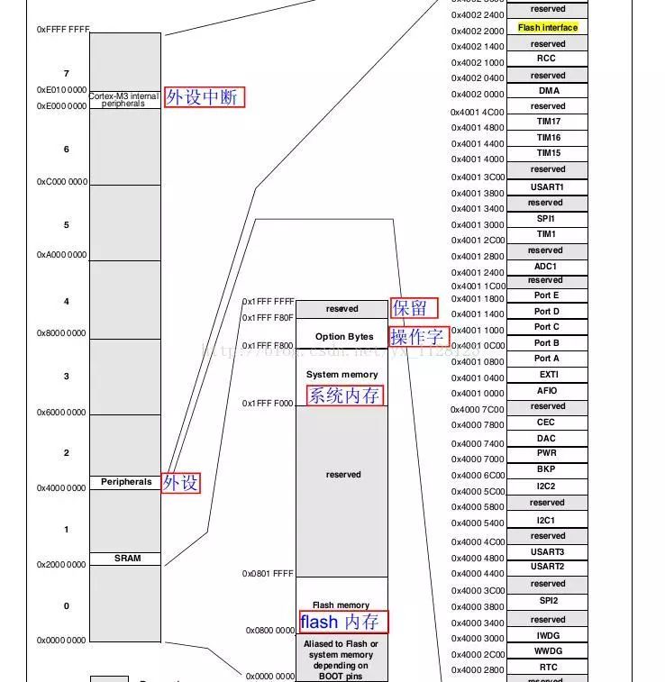
To implement IAP, place the IAP program starting at 0x08000000 and the application program at 0x08003000, with the interrupt vector table also at 0x08003000.
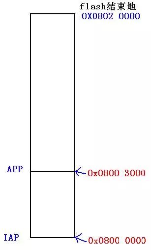
In the misc.h file, the macro NVIC_VectTab_Flash is defined as 0x08000000. Set IROM1 address in Keil options to 0x08000000 with a size of 0x20000 (128KB). IRAM1 address is 0x20000000 with a size of 0x2000.
Now, let's analyze the modified IAP code:
/************************************************* ******************************
* @function name main
* @function description main function
* @Input parameters none
* @output parameter
* @return parameters none
************************************************** *****************************/
int main(void)
{
// Flash unlock
FLASH_Unlock();
// Configure PA15 pin
KEY_Configuration();
// Configure serial port 1
IAP_Init();
// PA15 is low
if (GPIO_ReadInputDataBit(GPIOA, GPIO_Pin_15) == 0x00)
{
SerialPutString("=============================================================== =======================");
SerialPutString("= (C) COPYRIGHT 2011 Lierda =");
SerialPutString("= =");
SerialPutString("= In-Application Programming Application (Version 1.0.0) =");
SerialPutString("= =");
SerialPutString("= By wuguoyan =");
SerialPutString("=============================================================== =======================");
SerialPutString("");
Main_Menu();
}
// Otherwise execute the user program
else
{
// Check if the user program has been downloaded
if (((*(__IO uint32_t*)ApplicationAddress) & 0x2FFE0000) == 0x20000000)
{
SerialPutString("Execute user Program");
// Jump to the user code
JumpAddress = *(__IO uint32_t*)(ApplicationAddress + 4);
Jump_To_Application = (pFunction)JumpAddress;
// Initialize the stack pointer of the user program
__set_MSP(*(__IO uint32_t*)ApplicationAddress);
Jump_To_Application();
}
else
{
SerialPutString("no user Program");
}
}
Here are some important pieces of code:
First sentence: if (((*(__IO uint32_t*)ApplicationAddress) & 0x2FFE0000) == 0x20000000) // Determine if the stack address is within 0x20000000 - 0x20002000
This checks if the stack top address is valid by reading the first value in the interrupt vector table, which contains the stack top address. If correct, the user program has been properly initialized.

Second sentence: JumpAddress = *(__IO uint32_t*)(ApplicationAddress + 4); // This gets the reset address from the interrupt vector table.
Third sentence: Jump_To_Application = (pFunction)JumpAddress; // This casts the address to a function pointer type.
Fourth and fifth sentences: __set_MSP(*(__IO uint32_t*)ApplicationAddress); // Set the main stack pointer. Jump_To_Application(); // Execute the reset function.
The ported IAP code is available in my resource (for STM32F100CB chip): CSDN Link.
Third, let's briefly look at the startup code in the startup file. It helps us better understand IAP:
The following article is very good and highly recommended: Sina Blog.
Analyzing the startup process of STM32:
The current embedded application development process often uses C language, making the main function the starting point. However, how does the microcontroller find and execute the main function after power-on? Obviously, the microcontroller cannot locate the entry address of the main function from the hardware. Because C language is used, the address of variables/functions is allocated by the compiler at compile time, making the entry address of the main function not absolutely constant. The answer may involve a boot file, which is known as bootloader in English.
Regardless of performance, simplicity, or cost, each type of microcontroller must have a startup file. The purpose of the startup file is to execute the microcontroller from reset to start executing the main function. The most common 51, AVR, or MSP430 microcontrollers also have corresponding startup files, but the development environment often provides them automatically, without developers needing to intervene in the startup process, only starting the application from the main function. This is all right.
Moving to the STM32 microcontroller, whether using Keil uVision4 or IAR EWARM, ST provides ready-to-use boot files that can be directly used. Developers can import C files and directly develop C applications. This greatly reduces the difficulty of switching from other microcontroller platforms to STM32 and also reduces the adaptation difficulty of STM32 microcontrollers.
Compared to previous ARM generations, the startup mode of the new Cortex-M3 core architecture has changed significantly. After the ARM7/ARM9 core controller is reset, the CPU will start by taking the first instruction to execute the reset interrupt service routine from the absolute address 0x000000 of the memory space. However, the new Cortex-M3 core has three cases: 1) the interrupt vector table can be located in SRAM, 2) in FLASH, or 3) in the built-in bootloader area. The startup file provided by STM32's firmware library is used as a template for a brief and comprehensive analysis of the STM32 startup process.
Listing 1: "stm32f10x_vector.s", comments included:
DATA_IN_ExtSRAM EQU 0; Stack_Size EQU 0x00000400;
AREA STACK, NOINIT, READWRITE, ALIGN=3;
Stack_Mem SPACE Stack_Size;
__initial_sp;
Heap_Size EQU 0x00000400;
AREA HEAP, NOINIT, READWRITE, ALIGN=3;
__heap_base;
Heap_Mem SPACE Heap_Size;
__heap_limit;
THUMB;
PRESERVE8;
IMPORT NMIException;
IMPORT HardFaultException;
... (more lines follow)
The above code shows the STM32 startup code, written in assembly language. The main reason for this is explained below. Now analyzing from the first line:
Line 1: Define whether to use external SRAM. Line 2: Define the stack space size to be 0x00000400 bytes (1Kbyte). Line 3: Directive AREA, representing a segment. Line 4: Open up a memory space of size Stack_Size as a stack. Line 5: Label __initial_sp indicates the top address of the stack space. Line 6: Define the heap size to be 0x00000400 bytes (1Kbyte). Line 7: The pseudo-instruction AREA indicates a segment. Line 8: Label __heap_base, indicating the start address of the heap space. Line 9: Open up a memory space of size Heap_Size as a heap. Line 10: Label __heap_limit for the end of the heap space. Line 11: Tell the compiler to use the THUMB instruction set. Line 12: Tell the compiler to align with 8 bytes. Lines 13-81: The IMPORT instruction indicates that subsequent symbols are defined in an external file. Line 82: Read-only data segment defined, actually CODE region (assuming STM32 FLASH boot, then this is the start address of the interrupt vector table 0x8000000). Line 83: Declare the label __Vectors as a global label. Line 84: Label __Vectors indicating the interrupt vector table entry address. Lines 85-160: Create an interrupt vector table. Line 161: Reset Interrupt Service Routine. Line 162: Declare the reset interrupt vector Reset_Handler as a global attribute. Line 164: IF ... ENDIF structure determines whether to use external SRAM. Lines 165-201: The purpose of this part of the code is to set the FSMC bus to support SRAM. Line 202: Declare the __main label. Lines 203-204: Jump to __main address execution. Line 207: IF ... ELSE ... ENDIF structure to determine whether to use DEF: __MICROLIB. Lines 208-210: If DEF:__MICROLIB is used, __initial_sp, __heap_base, __heap_limit, etc., are assigned to the global attribute. Line 212: Define the global label __use_two_region_memory. Line 213: Declare the global label __user_initial_stackheap. Line 214: The label __user_initial_stackheap indicates the user stack initialization procedure entry. Lines 215-218: Save the stack top pointer and stack size, stack address and heap size to the R0, R1, R2, and R3 registers, respectively. Line 224: The program is finished.
The above is a complete analysis of the STM32 startup code, followed by explanations of a few small places:
1. AREA instructions: directive is used to define the code or data section, reference numeral followed by the property. One of the more important ones is "READONLY" or "READWRITE", where "READONLY" indicates that the segment is read-only and is associated with the internal storage medium of STM32. It can be seen that the segment with read-only attribute is stored in the FLASH area, i.e., 0x8000000 address. Rear. The "READONLY" indicates that the segment is a "read-write" attribute, and it can be seen that the "read-write" segment is stored in the SRAM area, that is, after the address 0x2000000. From this, you can know from the 3rd, 7th lines of code that the stack segment is in the SRAM space. From line 82, the interrupt vector table is placed in the FLASH area, and this is the first data in the entire boot code that is placed in the FLASH area. Therefore, you can get an important piece of information: 0x8000000 address is the top address of the stack __initial_sp, 0x8000004 address is the reset interrupt vector Reset_Handler (STM32 uses 32-bit bus, so the storage space is 4-byte aligned).
2. DCD instruction: The role is to open up a space, the meaning of which is equivalent to the address character "&" in C language. Therefore, the interrupt vector table created from line 84 is similar to the use of C language to define a pointer array, each of which is a function pointer, pointing to each interrupt service function.
3. Label: The word "label" is used in many places. The label is mainly used to indicate a certain location of a memory space, which is equivalent to the concept of "address" in C language. The address only represents a location in the storage space. From the perspective of the C language, the address of the variable, the address of the array, or the entry address of the function is essentially indistinguishable.
4. The __main label in line 202 does not represent the main function entry address in the C program, so line 204 does not jump to the main function to start executing the C program. The __main label indicates the entry address of an initialization subroutine __main in the C/C++ standard real-time library function. One of the main functions of the program is to initialize the stack (for program listing one, jump the __user_initial_stackheap label to initialize the stack), initialize the image file, and finally jump to the main function in the C program. This explains why all C programs must have a main function as the starting point for the program—because this is specified by the C/C++ standard real-time library—and cannot be changed, because the C/C++ standard real-time library is not developed outside. Source code. Therefore, in fact, under the premise that the user is visible, the program jumps to the main function in the .c file after the 204th line, and starts executing the C program. So far, you can summarize the startup files and startup process of STM32. First, the stack and heap size are defined, and the interrupt vector table is created at the beginning of the code area. The first entry is the top address of the stack, and the second entry is the reset interrupt service entry address. Then jump __main function, C/C++ standard library in real-time to complete the initialization of the user stack and so on, jump .c file in the C main function starts executing the program. Assuming that STM32 is set to boot from internal FLASH (which is also the most common case), the interrupt vector table starts at 0x8000000, the top-of-stack address is stored at 0x8000000, and the reset interrupt service entry address is stored at 0x8000004. When STM32 encounters the reset signal, it takes the reset interrupt service entry address from 0x8000004, then executes the reset interrupt service routine, then jumps to the __main function, and finally enters the main function to the world of C.
FC/PC Fiber Optic Fast Connector
Fc/Pc Fiber Optic Fast Connector,Optical Fiber Fast Connector,Fast Sc Connector,Fast Connector Ftth
Ningbo Fengwei Communication Technology Co., Ltd , https://www.fengweicommunication.com