This article introduces a practical high-voltage DC power supply circuit designed for stable long-term operation in industrial applications. The circuit is particularly useful when a wide dynamic range of output voltage is required, which traditional regulator circuits struggle to achieve. By integrating a differential amplifier as the sampling and comparison stage, the design significantly improves the regulation performance and stability of the power supply.
The circuit can operate with an input AC voltage ranging from 150V to 250V and provides a stable DC output between 150V and 250V. It features low power consumption, minimal temperature sensitivity, and excellent long-term reliability, making it ideal for continuous use in various environments.
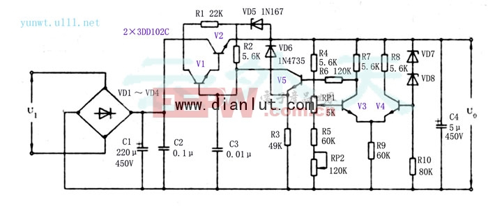
The power supply works by first rectifying the AC input using a bridge rectifier (VD1–VD4), followed by filtering through capacitors C1 and C2 to produce a DC voltage of approximately 330V. A pre-regulation stage consisting of resistor R1 and Zener diode VD5 ensures a stable reference voltage for the main regulator stage. This setup allows the output voltage to remain stable across a wide range of input conditions.
VD5 and R1 form a pre-regulator that maintains a steady voltage at the base of transistor V2, ensuring proper biasing of the composite transistor pair (V1 and V2). This configuration enhances the regulation accuracy and reduces the output impedance of the power supply. VD6 limits the collector-emitter voltage of V5, preventing it from exceeding safe levels. Meanwhile, VD7 and VD8, which have opposite temperature coefficients, help stabilize the output against thermal variations.
V1 and V2 are high-power transistors used in a composite arrangement to handle the load efficiently. A ceramic capacitor (C3) is included to suppress oscillations and improve overall stability. A differential amplifier is used as the core of the feedback system, allowing precise control of the output voltage by comparing it to a reference. This method ensures accurate regulation without being affected by environmental changes.
A variable resistor (RP1) is mounted on the panel to allow users to set the desired output voltage. RP2 is used during the initial adjustment phase to fine-tune the dynamic range of the output. Once properly adjusted, RP2 should be sealed to prevent accidental changes. For component selection, V1 and V2 must be chosen based on the maximum expected voltage and current. In this design, two 3DD102C transistors were selected to meet the requirements of U0 = 150–250V and I0 ≤ 50mA.
24V Dc Adapter,Adaptor Ac Dc 24V,24V Ac Dc Power Adapter,Adaptor Output 24V
ShenZhen Yinghuiyuan Electronics Co.,Ltd , https://www.yhypoweradapter.com