Medical and industrial applications often require isolation voltages of up to 2500 Vac or higher for patient and equipment operator personal safety requirements. The isolation barrier not only transmits power to the sensor device, but also transmits data to and from the device.
This article refers to the address: http://
Every data signal that traverses the isolation barrier requires isolation. Therefore, in these applications, designers can save money by choosing a serial bus instead of a parallel bus. The serial bus includes SPI, I2C, and Dallas single-wire serial buses.
The Dallas single-wire bus requires only one data line (plus ground) for two-way communication. Since optical isolators are unidirectional devices, a typical single-wire transmission requires two optocouplers, one for each direction of the data stream (and at least three optocouplers for the SPI and I2C buses).
The single-wire serial bus not only allows the transmission of bidirectional data streams, but also delivers power in parasitic power modes. An isolated transducer is used to power the sensor device. Thus, most designs require two optocouplers for the data interface: one optocoupler for feedback to the isolated power supply and one transformer for power isolation.
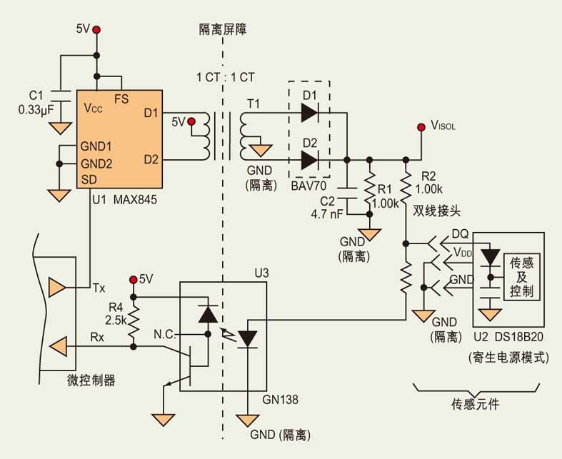
The circuit is shown in the figure. Only one isolation transformer driver (U1) and a single optocoupler (U3) are used in the circuit to minimize the number of devices used for isolation while maintaining a two-wire tap design.
 U1 provides isolated and virtually regulated power and enables the console to transfer data to a single-wire serial device on the other side of the isolated interface. The single optical isolator on the receive channel enables the console to receive isolated data from the single-wire serial device.
Note the following observation: At pin VISOI (upper right corner of the schematic), the voltage generated by U1 and transformer T1 is approximately 4.0V. D1 and D2 implement half-bridge rectification of the transformer secondary.
In U1, FS and VCC are connected so that the switching frequency of the device is rated at 860 kHz. Capacitor C2 filters the output to maintain the output level for a positive half cycle. R1 is used to discharge C2.
By utilizing the Dallas single-wire serial bus, the interface circuit provides isolation and two-way communication between the console microcontroller and the sensing components.
The main console microcontroller sends data to the single-line serial device by controlling the on/off of the SD end of U1. When data is not sent, U1 usually works and supplies power to the single-line serial device, which is represented as a logic high level for single-line devices. At this time, the voltage at the pin VISOL is approximately 4.0V.
When communicating, the master station applies a reset pulse to set SD high and turn off U1. Due to the turn-off of U1, the voltage at VISOL is reduced to the logic low level of the single-line serial device. Reasonably select the values ​​of R1, R2, R3, and C2 such that VISOI falls below the logic low threshold (0.8V) in approximately 5μs. (R1=R2=1.00kΩ, R3=2.00kΩ, C2=4.7nF will produce the test start value, and the final value depends on the selected optocoupler.) When U1 is working, the above four values ​​are reasonably selected. VISOI cannot be lower than the logic high threshold (2.4V) of a single-wire serial device.
When the console receives data from a single-wire serial device, the optocoupler (U3) is regulated by the VISOI level or the data terminal (DQ) of the single-wire serial device. When U1 is working, the LED in U3 lights up. This will force Rx low. When a single-wire serial device pulls DQ low, the LED goes out and Rx goes high. When U1 is turned off, Rx goes high, causing VISOI to decrease and extinguishing the LED. (The Tx and Rx logic on the microcontroller is the opposite of the logic on a single-wire serial device.)
Thus, an optocoupler, a transformer, and a Dallas single-wire serial line form an isolated sensing interface between the main console and the precision single-wire serial temperature measurement device. The circuit supports high voltage applications in medical and industrial applications while maintaining the lowest cost of connections and devices.
To satisfy the increasing demand of gigabit Ethernet POE Switch(GbE) networking, we have developed this series of gigabit Ethernet POE switch.
The gigabit Ethernet POE switch supports 120-watt PoE budget to drive up to 4 IEEE 802.3at compliant powered devices simultaneously. The PoE feature enables the NT-WG500-AT4 an efficient and cost-effective solution for SMB, SOHO and other similar fields to deploy the PoE network for wireless access points, IP-based surveillance cameras or IP phones anywhere easily and efficiently.
Fast Ethernet POE Switch,8 Port Switch,Fast Ethernet Switch POE,Managed Switch,Gigabit POE Switch, POE Switch Gigabit
Shenzhen N-net High-Tech Co.,Ltd , http://www.nnetswitch.com