Radio Frequency IdenTIficaTIon ( RFID ) technology is an automatic identification technology that has emerged from the 1990s and gradually matured. It uses non-contact two-way communication through RF coupling to achieve target recognition and data exchange.
During the movement of the RFID reader, the antenna's inductance and impedance variability cause unnecessary loss of the reader's transmission power and a decrease in the recognition ability. For the matching of reader antenna impedance, the research of some large foreign companies has turned to automatic matching, and there are more successful cases, while domestic application research mainly focuses on manual matching. With the development of integration technology, antenna and reader modules will be integrated, and new requirements will be put forward for antenna impedance matching. Manual matching is a time-consuming and complicated process.
Therefore, the automatic matching technology of antenna impedance will also become a development trend. In this paper, the manual matching method of antenna impedance is demonstrated, and a new antenna impedance matching method suitable for 13.56 MHz RFID reader is proposed in the case of maximizing the application of integrated components.
1 impedance manual matching technology
The RFID system uses an external antenna to communicate wirelessly with an electronic tag. The variability of the shape and size of the antenna fixture makes the input impedance of the antenna easily change with the change of the external environment, resulting in useless loss of transmission power. The standard impedance of RFID reader antennas in the world is generally 50Ω. The impedance matching target is set to (50 + j0) Ω. The antenna circuit is shown in Figure 1. It generally consists of three parts:
(1) Electromagnetic compatibility (EMC) filtering (L0, C0) circuit; (2) matching circuit including tunable capacitors C1, C2; (3) antenna.
The EMC filter circuit filters the harmonic interference when the carrier frequency is 13.56 MHz impedance conversion. It has a fixed resonant frequency, which is a combination of the actual data rate and the highest subcarrier frequency. For example, when encoding with Manchester, the highest data rate is 424 kbit/s, the frequency is 848 kHz, and the resonant frequency is 14.408 MHz.
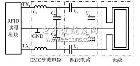
Figure 1 Antenna circuit block diagram
At a carrier frequency of 13.56 MHz, the antenna is manually tuned by measuring the reflection coefficient of the antenna line at both points TX1 and TX2 (ie, parameter S11) until the input impedance of the antenna circuit reaches the target. The equation is as follows:
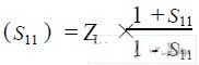
Another ZL = 50W, it can be seen that to make (S11) = 50Ω, S11 must be 0.
Manual tuning is to alternately adjust the values ​​of capacitors C1 and C2 while observing the curve change until S11 is equal to 0 at the desired frequency point. Fig. 2 is a graph showing the change of the reflection coefficient of an antenna circuit when the frequency is changed between 10 and 20 MHz, wherein the point of 13.56 MHz is marked, and the value of S11 is approximately 0, which satisfies the matching requirement.
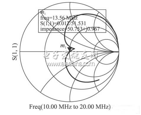
Figure 2 Manually matched antenna smit diagram
Driver For FUJI SMT Machine, in stock, original and new.
FUJI CP6 SERVO DRIVER SAA1340 DR1B-02AC
FUJI CP643 D DRIVER EEAN1910 CACR-44-FK1CSY1A
FUJI GLV DRIVER PDT-J02-412
FUJI GL-V DRIVER SAA1080 CACR-SR10BC1KSY262
FUJI IP3 Y DRIVER SAA1220 DR1-04ACY9
FUJI NXT M3 M3S M6 SERVOPACK SGDZ-BS60AN7A-FK JUSP-CON08AE7AA
FUJI NXT M6S SERVO AMP JUSP-CON14AE7AA SGDZ-BS51AN7A-FK
FUJI NXT SERVOPACK SGDZ-BS60AN7A-FK JUSP-CON08AE7AA
What's more, the following products can be found in our company:
Smt Filter
Smt Machine Filter
Smt Tape Feeder Parts
Original Smt Feeder
Original Smt Cable
Smt Machine Cable
Smt Cable
Driver For FUJI SMT Machine
Shenzhen Srisung Technology Co.,Limited , https://www.sr-smt.com