Abstract: In order to prevent signals from the terrestrial UHF channel from reaching the satellite DBS tuner and reducing its sensitivity, a high-pass filter is required at the input of the set-top box. Based on the analysis of satellite TV signals and terrestrial signals, the performance indicators of filters suitable for satellite DBS modulators are given; using the FDATool in Matlab, IIR high-pass filters that meet the requirements of the indicators are designed and the amplitude Frequency and phase frequency response curves. The simulation results show that the performance indicators of the design results meet the requirements, and the design process is simple and easy.
introduction
Cellular mobile phone signals are in the 825-895 MHz frequency band, plus terrestrial television broadcasting, they can find the channel from the satellite feeder into the set-top box. These "blocking" signals can be coupled into the antenna through a side lobe of the dish antenna (that is, the directivity of the antenna is not ideal), or coupled to the dish antenna only by virtue of its short distance and high power. In the combined band feed cable connected to the set-top box, the satellite DBS band is 950-2150 MHz, and the terrestrial TV band is 54-860 MHz. A high-pass filter is required at the input of the set-top box to prevent the UHF channel signal from reaching the satellite DBS tuner and reducing its sensitivity.
1 Design of digital filter
FDATool (Filter Design & Analysis Tool) is a special filter design and analysis tool for Matlab signal processing toolbox. It is easy to operate and flexible, and can use a variety of methods to design FIR and IIR filters. Enter FDATool in the Matlab command window and press Enter to pop up the FDATool interface, as shown in Figure 1.
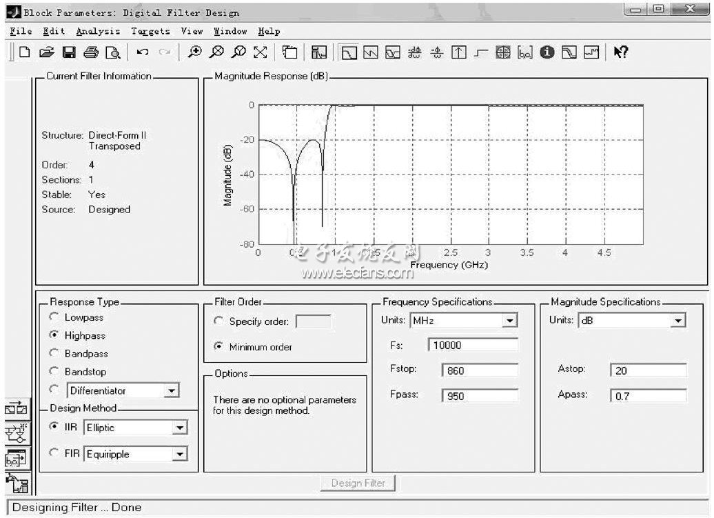
Figure 1 FDATo ol interface and filter design parameter settings
Since the frequency band of the satellite signal is very wide, a high-pass filter is selected. In this example, the design of IIR is selected. The requirement is to attenuate the signal in the 54-860 MHz frequency band by 20 dB, while the insertion loss of the satellite L-band signal (950-2150 MHz) passing through does not exceed 0.7 dB. The upper boundary (860 MHz) of the terrestrial signal band is very close to the lower boundary (950 MHz) of the satellite signal band. For such a small transition band, an elliptic filter is chosen. Because of the problems of cost and component error, the minimum order is selected in order selection.
As shown in Figure 1, check and fill in the performance indicators of the above filters on the FDATool interface. After setting, click Design Filter at the bottom of the window. At the top of the window, you will see the amplitude frequency and phase frequency response of the designed filter as shown in Figure 2 and Figure 3. You can also see the phase frequency response, group delay, impulse response, step response, zero pole configuration of the filter through the menu option Analysis. After the design is completed, save the result as ellipitc.fda file.
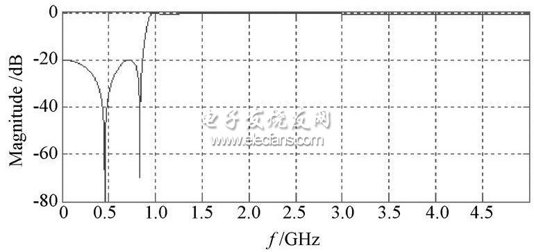
Figure 2 Amplitude-frequency response curve of the filter
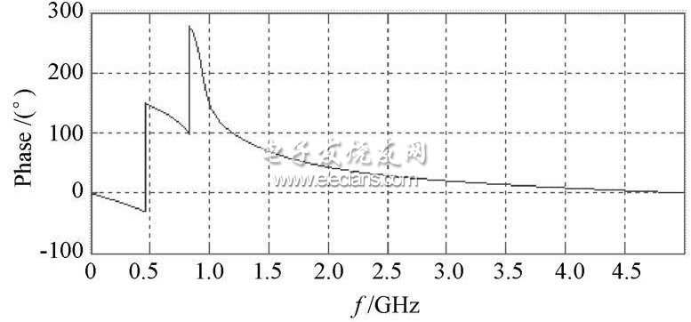
Figure 3 Phase frequency response curve of the filter
1.High model conversion efficiency,more than 19%,reducing installation costs and maximizing the kwh output per unit area. 2.power tolerance of -3% to +3%minimizes PV systems mismatch losses.
3.Excellent performance under low light environments.
4.High transparent,low-iron,tempered glass,and antireflective coating.
5.Five years warranty,25 year using life,good quality.
Mono Panel,Mono Solar Panels,Monocrystalline Solar Panels
Yangzhou Beyond Solar Energy Co.,Ltd. , https://www.ckbsolar.com