Comprehensive test of LTE system with channel emulator
In just a few years, the mobile data business has been so slow from the beginning that it was not practical, and has developed to the point where it is as easy to use as Wi-Fi. As consumers and business application developers are eager to find the methods needed to take advantage of improved mobile data services, technology experts are also striving to provide newer, faster, and more powerful broadband wireless networks to support this demand.
With users, mobile phone manufacturers, application developers and service providers all focusing on the next big application that will drive market growth, the focus of the current mobile phone industry has shifted from "least dropped" to "fastest network" "on. This increase in demand mainly comes from data transmission.
Existing wireless network capacity is limited, so in order to maintain this growth, the network needs to have the following characteristics: smooth, all-IP (Internet Protocol) architecture, greater capacity, lower cost per bit, faster connection, Shorter latency and improved video capabilities. As data services continue to explode, how can manufacturers and service providers ensure that new equipment and new applications provide the quality, throughput, and performance that users expect?
Several leading industry organizations are developing technical standards designed to promote the development of 4G broadband wireless networks, enable these increasingly complex devices to function properly, and enable the implementation of these demanding applications, including what is known as long-term evolution (LTE) and 802.16 e-2005 or mobile WiMAX. LTE and mobile WiMAX have a major common feature. They both use orthogonal frequency division multiple access (OFDMA) and multiple input multiple output (MIMO) technologies. Essentially, OFDMA and MIMO can provide a higher level of data transmission capability with a smaller bandwidth.
In terms of the impact of the air interface (the physical path of the RF signal between the transmitter and receiver), OFDMA and MIMO systems can improve the overall performance of the RF transmitter and receiver. The radio channel will be affected by many aspects, such as signal delay, attenuation and obstacles. These factors may combine to improve the signal transmission conditions, or may damage the transmitted signal, that is, they can have positive and negative effects on the overall channel throughput / data rate.
OFDMA is a robust digital modulation mechanism that can improve overall spectrum efficiency. To reduce multipath interference, it uses fewer symbol rates per carrier, but it also uses multiple carriers to increase the data rate. OFDMA transmits multiple symbols simultaneously on several carriers, rather than transmitting one symbol at a time. The subcarriers are distributed at multiple frequencies and are "orthogonal" to avoid any interference caused by adjacent subcarriers.
MIMO systems utilize multiple transmit and receive data paths to significantly increase throughput, expand link coverage without additional bandwidth or increase transmit power. Several different technologies can be used to implement MIMO, including spatial multiplexing, adaptive antenna system (AAS), space-time coding (STC), and maximum ratio combining (MRC).
Spatial multiplexing generally improves performance by increasing the capacity of the system. AAS expands the network coverage by directing the signal power to the user or making the influence of the interference source zero. STC (diversity transmission) and MRC (diversity reception) send and receive multiple copies of the same user data, respectively, to avoid damage such as attenuation.
Traditional test methods and limitations
With the introduction of complex and specialized new hardware and new software, the challenges of testing are increasing. Testing tools are an area that has undergone fundamental changes, especially the tools used to verify the testing of new generation RF transmitters and receivers have undergone tremendous changes. There are three methods that can be used to test the performance of the transmitter and receiver: direct cable connection, over-the-air test, and connection via the channel emulator, as shown in Figure 1.
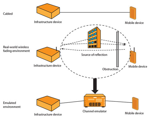
Figure 1: Three methods used to test the performance of the transmitter and receiver.
RF testing has traditionally been carried out in the laboratory first, followed by space fixed-point testing and field testing. Generally, the first step in testing an RF circuit is to directly connect the RF transmitter and receiver with RF cables and connectors. Although this test configuration allows for a controlled and repeatable method to test the performance of the transmitter and receiver, it is an ideal, unrealistic scenario.
Cable-based testing cannot meet the more complex test requirements needed to simulate real-world dynamic conditions when signals are transmitted in space and wireless devices are in motion. Because MIMO technology relies on real-world behavior to improve operational performance, in some test cases, laboratory / cable-based tests are ineffective and inappropriate in many other tests.
Over-the-air (OTA) testing refers to the process of propagating radio frequency signals through space to a physical remote receiver. It can provide a certain level of performance measurement, but it cannot provide consistent accuracy and repeatability. OTA tests are generally conducted in large rooms or in the field, and their conditions are not completely controllable or repeatable, resulting in different results for different tests. The effort to build hundreds of complex test environments under various noise and different interference field conditions is a time-consuming and costly task.
Advanced 4G testing: channel simulation
The introduction of LTE and mobile WiMAX technologies, especially their OFDMA and MIMO features, require advanced testing capabilities and tools to ensure that product designs meet or exceed the performance expectations of 3GPP / 802.16e. The complex physical layer and open access requirements of 4G technology based on MIMO and OFDMA also put forward higher requirements on wireless performance / interface quality, thus making 4G testing more complicated than ever.
To make up for the differences between laboratory and OTA testing, channel emulators are often used to accurately characterize the impact of multi-channel RF interactions on consistency, performance and interoperability in a laboratory environment based on MIMO and OFDMA systems .
Using a complex channel model and multiple programmable parameters, the channel emulator replicates and reproduces real-world channel propagation conditions in a controlled and repeatable manner, thereby supporting manufacturers and service providers to test equipment under real-world conditions Minimize the time and expense of testing in the "real" world.
By reproducing the real-world channel conditions in the laboratory, the channel simulation test process for base stations and mobile devices can be greatly simplified and efficiency can be significantly improved. Channel emulation is the key to effectively testing LTE, mobile WiMAX, or any MIMO-based system. From initial research and design, to system integration, quality assurance, and even certification and competitive benchmarking, channel simulation is required. Using a channel emulator, RF design and performance can be verified, test coverage can be expanded, test times can be reduced, and higher quality products can be brought to market in a relatively short period of time.
Appropriate channel emulator
To meet the testing needs of the latest and emerging mobile wireless technologies, it is critical to assess whether the channel emulators selected for these jobs meet the diverse needs for conformance, function, performance, and interoperability testing. As mentioned above, the latest wireless broadband technology uses OFDMA, which transmits on high-order modulation up to 64-state quadrature amplitude modulation (64QAM), and also uses MIMO technology using multiple antennas.
Therefore, the channel emulator needs to have RF fidelity and scalability to process and test these functions. Several items listed below are some of the key technical indicators and capabilities that engineers should focus on when selecting channel emulators for test equipment and networks. Figure 2 shows an example of testing using a channel simulator. With the full bidirectional MIMO channel, the eNodeB can be connected to multiple user equipments (UEs). The channel simulation environment can provide a different path for each user, and at the same time provide real-world scenarios with attenuation in both the downstream and upstream. The characteristics of the channel simulation environment are given below.
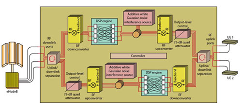
Figure 2: An example of testing using a channel emulator.
Scalability / multi-channel: Up to 4 × 4 structure to support spatial multiplexing, space-time coding / maximum ratio combining and beamforming. Flexible configuration: Including the ability to configure point-to-point and point-to-multipoint, unidirectional and bidirectional for throughput and switching tests. Bidirectional: Time Division Duplex (TDD), Frequency Division Duplex (FDD), beamforming, etc., all require both real-world uplink and downlink directions. High RF fidelity: wide enough error vector magnitude (EVM), noise floor, and dynamic power range without impeding the test. Channel model: To test various scenarios, standard and user-defined channel models are required. Real-time dynamic channel modeling: long model repetition and playback time. Control and automation: Simulation control based on graphical user interface (GUI) and scripts to build test automation. Easy to use: simple setup, configuration and test execution and collection of test results to support independent or integrated testing.
Summary of this article
Complex broadband wireless technologies such as LTE and mobile WiMAX with MIMO and OFDMA technologies, coupled with users' high expectations for the newly launched mobile broadband services, have driven the need for more extensive and extensive testing to ensure network interoperability and performance. Using a channel simulator to test equipment using the reconstructed real-world channel conditions greatly simplifies the implementation of a more comprehensive test.
By providing a broad and cost-effective solution to test whether RF and MIMO algorithms are working properly and predict the performance of products based on MIMO technology in real-world environments, laboratory-controlled channel simulation can accurately characterize devices and networks The impact of wireless interaction on consistency, performance, and interoperability. Only through such comprehensive testing can manufacturers ensure that new, data-intensive applications and devices can successfully play a role in 4G mobile networks.
T8 LED Tube Light is available in 13W 18W 24 W 30W 36W, used 2835 SMD, in 600mm 900mm 1200 mm 1500mm 1800mm 2400mm length available.The tube is CE, RoHS certified. T8 uses G13 end caps. The voltage range is from 85 to 277 VAC. T8 Tube has around 90-150lm/w lumen output. The power factor is greater than 95%. The CRI is great than 70. The tube lens including clear cover and frosted cover . Color Temparature is 2700-6500K . Life up to 30,000 hours. Types are divide to high efficiency Tube, Radar Sensor Tube,Motion Sensor , PIR Sensor and TRIAC Dimmable Tube.
T8 Tube,T8 LED Tube Light Integrated, 2FT LED Tube T8,4FT LED Tube T8
Shenzhen Ri Yue Guang Hua Technology Co., Ltd. , https://www.ledlightinside.com