1 technical management
1. 1 drawings, specifications and contractual agreements
In the process of quality acceptance of construction projects, one of the main contradictions between lamp and lighting acceptance is the consistency of the drawings, construction technical plans and actual conditions of on-site construction. For the implementation of technical standards, different understandings of contract and drawing changes affect the process of handover, and even lead to failure of acceptance.
The construction party shall strictly follow the approved drawings, relevant technical regulations and the requirements of the contractual provisions. The necessary technical changes in the construction shall be recorded in the form of agreement and signing and shall be properly kept as additional technical documents. All supplementary technical documents must comply with the relevant standards, otherwise they are invalid documents and cannot be used as a technical basis. The current national standards corresponding to the standards for construction and acceptance of lamps and lighting projects are GB50303 Building Electrical Construction Acceptance Specifications and GB50411 Building Energy Efficiency Engineering Construction Acceptance Specifications.
1. 2 lamps and their accessories
In the construction acceptance, the material and specifications of the materials often cause controversy, and the main control reference point for the construction quality is rejected. Electrical materials commonly used in lighting and lighting energy-saving projects include lighting fixtures, light sources and their ancillary facilities, as well as wires, cables and low voltage busbars. Due to the concealment of electrical construction, the transformation after construction will cause great manpower and material waste, and the transformation implemented will directly affect the quality and structure of the main building project.
In order to avoid such problems, we must first grasp the acceptance inspection of materials, so that all materials meet the drawing requirements and national standards; secondly, pay attention to the collection and preservation of technical information of electrical materials, including the factory certificate, instructions, acceptance and verification. Records and quality certification documents are used as proof materials for engineering quality acceptance. If necessary, samples of electrical materials may be retained for concealed works and submitted as acceptance data.
The choice of lighting source, luminaire and its attachments must meet the design requirements. When the design is not required, it should comply with the relevant provisions of the architectural lighting design standard GB50034. It should also meet the following inspection requirements: the power consumption of the ballast is not more than 15% of the nominal power of the light source, the harmonic content is not more than 20%; the overall power factor of the gas discharge lamp must not be less than 0.
2 technical measures
2. 1 natural lighting and artificial light source
In the concept of modern building energy conservation, the application of renewable energy (solar energy, wind energy) has received more and more attention. The pursuit of natural light in lighting design is rapidly developing in architectural design. The use of glass curtain walls, glass skylights and roofing in buildings has increased. One of the problems caused by the lighting is the contradiction between lighting and heat preservation and heat insulation. It can not effectively guarantee the insulation performance of the building, but increases the investment in building heating and cooling. The second problem lies in the light source and effective reflection artificial light source, that is, the coordination of natural lighting and artificial light source. Specific parameters can be found in the literature.
2. 2 lamps and ballasts
2. 2. 1 luminaire efficiency and ballast efficiency
Lamps and ballasts require full inspection in the quality acceptance of energy-saving projects. At present, in the architectural decoration, due to the excessive pursuit of the appearance of the effect, often the qualified light source can not meet the requirements of GB50411.
The main reason is that the selection of the protective cover, the transparent cover and the grille is unreasonable in terms of light transmission. See the technical requirements.
Fluorescent lamps and high-intensity discharge lamps luminaires allow for < 1> luminaire outlets in the form of open hoods (glass or plastic) transparent matte, prism grille or translucent hood fluorescent lamps 72% 65% 55 % 60% - High-intensity gas discharge lamps 75% - 60%
Ballast energy efficiency limit value < 1> Nominal power ( W ) 18 20 22 30 32 36 40 Ballast energy efficiency factor ( BEF ) Inductive type 3. 154 2. 952 2. 770 2. 232 2. 146 2. 030 1. 992 electronic type 4. 778 4. 370 3. 998 2. 870 2. 678 2. 402 2. 270 In construction, the lampshade is usually the key to affect the efficiency of the luminaire. The matching performance of the ballast and the luminaire is the main factor affecting the performance of the ballast.
2. 2. 2 Harmonic components of the luminaire
Fluorescent lamps, high-pressure mercury lamps, high-pressure sodium lamps and other gas discharge lamps are nonlinear components that generate high-order harmonics in the power system. High-order harmonic currents pass through the power supply transformer, which significantly increases the core loss of the transformer, thereby causing the transformer to overheat and shorten. Its service life. The higher harmonic current increases the current on the zero line, increases the energy consumption of the power line, makes the metering of the inductive watt-hour meter for calculating the electricity rate inaccurate, and may also cause the voltage resonance of the power system, thereby causing the on-line Voltage, breakdown of the insulation of the line equipment. Higher harmonics also interfere with communication devices and circuits in the vicinity.
The harmonic content of the luminaire should be met, and the inspection and acceptance should be based on technical data and test reports.
Harmonic component of the lighting device limits the harmonic order n The maximum allowable harmonic current expressed as a percentage of the input current at the fundamental frequency. Remark 2 3 30 is the power factor 5 10 7 9 5 11 n 39 (only in odd harmonics) 3
2. 2. 3 Installation and control of lamps
The public lighting area of ​​large public buildings should be controlled centrally, partitioned and grouped according to the building conditions and natural lighting conditions, and the necessary dimming control should be installed.
The hotel’s rooms should have an energy-saving control switch.
For general lighting of stairs and walkways where residential buildings have natural lighting, energy-saving self-extinguishing switches should be used. Emergency lighting is not included here.
When the indoor light has more than two columns, the controller and the light fixture correspond to the orientation, and the controlled light column is parallel to the side window; the electric classroom, the conference room, the multi-function hall, the lecture hall and the like are grouped according to the proximity and away from the podium.
2. 3 energized conductor
2. 3. 1 Cable and wire cross section does not meet energy saving requirements
On the one hand, the conductors in the design cannot meet the requirements of safe current carrying capacity and mechanical strength; on the other hand, the conductor cross-section selected according to the safe current carrying capacity and mechanical strength cannot meet the requirements of energy-saving indicators.
In the case of such problems, it is necessary to re-route the wires, which will affect the delivery period of the building. Especially after the implementation of GB50411, the technical indicators that can meet the requirements of the previous one may not meet the latter requirement, and misunderstandings are formed in engineering design and construction.
GB50411 specifies the maximum resistance value of the wires in the building. During the construction, the incoming wires shall be inspected according to this requirement. See the resistance values ​​of some wires.
In the construction, the wire should be used strictly in accordance with the standard inspection, to prevent the increase of line loss caused by the inferior wire, affecting the energy-saving acceptance, and even serious heat formation poses a safety hazard.
Maximum resistance value of 20 o'clock round copper wire (not metallized) Nominal cross section (mm) 1. 5 2. 5 4 6 10 16 25 35 50 Maximum resistance (km) 12. 1 7. 41 4. 61 3. 07 1. 83 1. 15 0. 727 0. 524 0. 387
2. 3. 2 The wire that meets the energy saving requirements has a fever
Wires that are fully qualified for quality and energy conservation have serious heat generation during construction acceptance and commissioning. This is a safety hazard caused by electrical construction process errors, and it also increases the power loss during operation. In energy-saving acceptance, it is often easy to ignore, causing electrical failure of buildings.
The reason for the heat is that the AC single-phase or three-phase single-core cables are laid side by side, or the wires and cables are fixed with iron clamps. In the circuit thus installed, after the conductor is energized, a ferromagnetic circuit is formed, and the larger the current in the conductor, the more severe the heat generation. In the process of fault checking, the current carrying capacity of the measured conductor does not exceed its rated value, so that the fault point cannot be found. Especially for the dark laying of wires, it is more difficult to find the point of failure in the field.
The correct way is: single-phase cable or three-phase cable after phase separation, the core should be arranged according to the trilobal shape to avoid the formation of ferromagnetic circuits.
Use a conductive material that is non-conductive or does not form a closed loop as a fixed line card.
2. 3. 3 There is a large current on the zero line
The current on the zero line is large, and within the current limit range, the line loss will increase. Exceeding the load current will cause an accident.
GB50411 clearly defines the imbalance of the three-phase load, which is intended to reduce the current on the zero line during operation and achieve the purpose of energy saving. At the same time, the three-phase load imbalance will directly affect the luminous efficiency and service life of the lighting fixture. Therefore, the maximum phase load should not exceed 115% of the average value of the three-phase load, and the minimum phase load should not be less than 85% of the average value of the three-phase load.
In the construction of electrical and lighting construction, reasonable phase matching should be made to balance the three-phase load. Since the building load is mostly single-phase load, phase separation is a major electrical problem in construction.
2. 3. 4 power distribution bus heating
The busbar of the substation in operation is hot, increasing losses and causing voltage loss.
This is also a fault caused by an electrical construction process error. Before the busbar is installed, the quality and material of the busbar crimping joints should be strictly checked and should meet the requirements of the literature <2>. The tightening torque of the busbar lap bolts shall comply with the requirements.
Tightening torque of busbar lap bolts < 1> Bolt size M8 M10 M12 M14 M16 M18 M20 M24 torque value (Nm) 8. 8 10. 8 17. 7 22. 6 32. 4 39. 2 51. 0 60. 8 78 5 98. 1 98. 0 127. 4 156. 9 196. 2 274. 6 343. 2
3 power quality
After the installation of the project is completed, the low-voltage distribution system should be commissioned. After the commissioning is completed, the quality of the low-voltage distribution power supply should be tested. The following problems are usually encountered during testing.
3. 1 large voltage deviation
The standard value is 220V + 7%, - 10%. When the voltage difference is large, make the following adjustments.
(1) Correctly select the voltage tap of the transformer or use the on-load tap changer
If the voltage is too high, the tap changer should be switched to a + 5% U 1N tap. If the voltage is low, the tap-changer should be switched to a -5% U 1N tap. This is the most common and convenient pressure regulation measure in practice. However, the switching voltage tap must be powered off, so it cannot be operated frequently. If the equipment used in the electric load has strict voltage requirements, the unloaded voltage regulating transformer can not meet the requirements, and when the separately installed voltage regulating equipment is technically unreasonable, the on-load voltage regulating transformer can be used to make it The voltage is automatically adjusted during normal operation to ensure voltage stability.
(2) Reduce system impedance
The voltage drop of each component in the power supply system is proportional to the impedance of each component. In building power supply, increasing the line cross section or replacing the overhead line with a cable can reduce the system impedance and reduce the voltage drop, thereby reducing the range of voltage deviation. .
(3) Try to balance the three-phase load
In the three-phase four-wire system, if the three-phase load distribution is not balanced, the potential of the neutral point of the load terminal will be shifted, causing some phase potential to rise, thereby increasing the voltage deviation of the line.
(4) Using reactive power compensation device
3. 2 public grid harmonics high
380V grid nominal voltage, voltage total harmonic distortion rate of 5%.
When the harmonic content is large, the following method is used.
(1) The larger the short-circuit capacity of the grid-powered grid with a large short-circuit capacity, the stronger its ability to withstand nonlinear loads.
(2) The three-phase rectifier transformer adopts Yd or Dy coupling so that at least one of the primary or secondary windings is connected by a triangle ( ), and this coupling can eliminate the higher harmonics of integer multiples of 3.
(3) Increasing the number of phases on the secondary side of the rectifier transformer. The more the number of phases on the secondary side of the rectifier transformer, the more the number of rectified pulses increases, and the more harmonic components whose times are lower are eliminated.
Increasing the number of rectified phases is quite significant for suppressing higher harmonics.
(4) Installation of shunt filter The shunt filter, also known as the tuned filter, consists of multiple sets of R-L-C series resonant circuits that can tune the harmonics that need to be eliminated. Since the branch impedance is small during series resonance, the harmonic current of the relevant number can be shunted (absorbed) by the resonant branch without being injected into the power grid.
(5) Installation of static compensation device (SVC) for large silicon rectifier equipment, SVC can also be installed to absorb higher harmonic currents to reduce the harmonic interference generated by these consumers.
4 ends
Lamps and lighting are important links in architectural and architectural decoration projects. Reasonable selection of lamps and their accessories to ensure the quality of power supply and to ensure the construction process and material quality is the key to building energy-saving projects.
Cheap 12 Layers PCB stackup and thickness
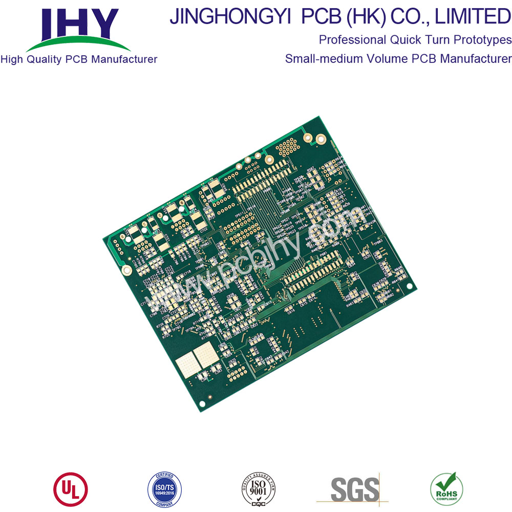
We are one of the few manufacturers in China that can manufacture 12-layer PCB boards on a large scale.
The 12-layer board can usually be manufactured smoothly on a 1.6mm thick FR-4 board. But we've seen more 14- to 16-layer boards are being fabricated into 1.6mm thick boards, but the number of manufacturers that can produce them is limited to manufacturers that can produce HDI boards. Those who can produce HDI boards are increasing.
12 Layers PCB– Heavy industry boards or boards with may tracks
For industrial PC design, 12-layer circuit boards are more popular. Compared with other multi-layer circuit boards, such as four-layer circuit boards, 8-layer circuit boards, 10-layer circuit boards, The price of the 12-layer PCB is still reasonable.

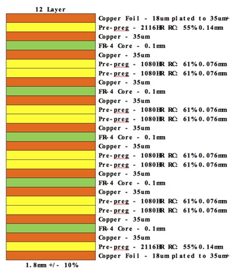
12 Layer PCB stackup and thickness
12 Layer PCB Stack Up
Top Layer †18um Copper Foil (plated to 35um+)
Preâ€Preg †1 x 2116
Layer 2 & 3 †0.13mm Frâ€4 Core with 35um/35um Copper
Preâ€Preg †1 x 2116
Layer 4 & 5 †0.13mm Frâ€4 Core with 35um/35um Copper
Preâ€Preg †1 x 2116
Layer 6 & 7 †0.13mm Frâ€4 Core with 35um/35um Copper
Preâ€Preg †1 x 2116
Layer 8 & 9 †0.13mm Frâ€4 Core with 35um/35um Copper
Preâ€Preg †1 x 2116
Layer 10 & 11 †0.13mm Frâ€4 Core with 35um/35um Copper
Preâ€Preg †1 x 2116
Bottom Layer †18um Copper Foil (plated to 35um+)
Stardand 12 Layer PCB 1.6mm +/†10%

12 layer stackup – 4 GNDs
I use this stackup a lot, provides GND shielding of high speed signals and has tightly coupled Power-Ground planes:
Signal / Solid GND plane / High speed signals and important buses / Solid GND plane / Power / Power or Mixed with signals / Power or Mixed with signals / Power / Solid GND plane / High speed signals and important buses / Solid GND plane / Signal
12 layer stackup – two additional signal layers
Signal / Solid GND plane / Signal / Signal / Solid Power Plane / Power or Mixed with signals / Power or Mixed with signals / Solid Power Plane / Signal / Signal / Solid GND plane / Signal
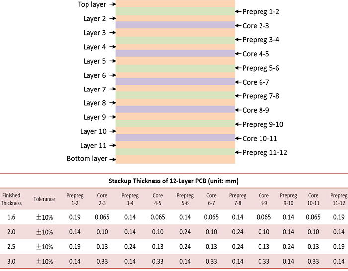
12 layer PCB stackup thickness


12 layer PCB Features and benefits
- Lead-free surface finish and lead-free components
- Long storage time (vacuum and anti-static packaging)
- Improved the speed of signal transmission
- Fast on time delivery
- UL certified and RoHS compliant
- Prototype PCB Manufacturing
12 layer PCB Application
DSL Modem, Solar Battery Charger, Vehicle Tracker, GPS Receiver, Wi Fi Antenna, Bluetooth USB Hub, USB Wireless Router, SMS Modem, Multicoupler Antenna, Phone systems.
12 Layer PCB
Printed Wiring Board,Custom Printed Circuit Board,12 Layer PCB,Custom 12 Layer PCB
JingHongYi PCB (HK) Co., Limited , https://www.pcbjhy.com