Core tip : Wireless charging is just around the corner, and it has now expanded to medical and other portable devices. This article mainly introduces the wireless charging design and implementation of portable medical equipment.
Imagine that you are a medical technician in an emergency room in a big city. You shuttle between the various wards, using portable diagnostic equipment to assist the medical staff to make a diagnosis. There is a lot of work pressure and there is a constant flow of patients. You simply do n’t have time to find a socket and plug your equipment. You are probably willing to put the device in one place and let it charge automatically. This way you can get to the next patient or injured person, who needs fast and efficient medical staff. Fortunately for you and the patient, wireless charging is already an off-the-shelf technology.
standard
Industry standard specifications are leading the development of wireless charging. The wireless charging alliance (WPC) standard is also called Qi (pronounced "odd"). This specification is divided into three core parts of the system: the power transmitter, the power receiver, and the communication protocol between the two devices. The main features of this standard are (see Figure 1):
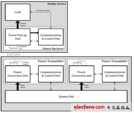
Figure 1: Block diagram of wireless charging system (Source: Wireless Charging Alliance website)
(1) A non-contact power transmission method from the base to the portable device. The physical basis of this method is the near-field electromagnetic induction between the coils.
(2) Use a secondary (or receiving) coil to transmit approximately 5W of power.
(3) The operating frequency range is 110Hz to 205kHz.
(4) There are two ways to place the portable device on the surface of the base: one way is to place the portable device at a specified position on the surface of the base, and the base provides energy through one or several fixed positions on the surface; free positioning allows portable The device is randomly placed on the surface of the charging station to provide energy from anywhere on the surface.
(5) Very low standby power consumption can be achieved, depending on the specific implementation method.
(6) The system can be flexibly integrated into a portable device.
Energy transfer process
A simple communication protocol enables the portable device to fully control the energy transmission process. The energy transmission process is divided into 4 stages:
(1) Selection stage: The power transmitter monitors the charging interface and detects whether the device to be charged is put in place. If no device is detected, the power transmitter will constantly ping the power receiver. If no device to be charged is detected within a given time, the power transmitter will enter standby mode.
(2) Ping stage: similar to sonar, the power transmitter sends out a digital ping signal to detect rechargeable devices. If the device is detected, the power transmitter maintains the power signal at the level of the ping signal, and then enters the identification and configuration phase. If no device is detected, the power transmitter returns to the selection phase.
(3) Identification and configuration stage: The power transmitter negotiates with the power receiver to determine how much power is provided to the device that needs to be charged on the interface. If the device is removed from the interface, the power transmitter returns to the selection phase.
(4) Power transmission stage: The power transmitter provides energy to the power receiver, and the required current is adjusted according to the feedback of the power receiver. When an abnormal situation occurs during the power transmission process, the safety function will turn off the power transmission in time and return to the selection stage.
This standard has been supported by more than 90 companies in various fields of the electronics industry.
technology
Wireless charging uses the principle of near-field electromagnetic induction to transfer energy from a charging base (pad) to a portable device. At changing distances, the transmitter coil (Tx) in the charging pad transmits energy to the receiver coil (Rx) embedded in portable devices such as mobile phones. The transmitter / primary coil in the charging pad generates an electromagnetic field similar to a traditional transformer when it is powered up, and the induced current flows through the secondary coil on the portable device. On the receiver side, the power receiving unit converts the electromagnetic field into electrical energy again to charge the battery of the device). The transmitter and receiver communicate with each other to control the charging process.
Vishay Dale Electronics ’IWAS series of Qi wireless charging receiver coils / shields are the first commercial wireless charging coils that can be used for devices that comply with WPC specifications. The efficiency of the IWAS series reaches 70% or higher, provides a high permeability shield for the receiving coil, blocks the charging magnetic flux, and prevents it from damaging sensitive devices or batteries. The performance of IWAS series wireless charging receiver coil / shield will not be adversely affected by permanent magnets.
Bedroom Lights, Ceiling Light, Ceiling Light Replacement, Led Ceiling Lights
Shenzhen Dianjiang Engineering Co. LTD , https://www.isourceled.com