Power factor has never been a problem. In the past, there were regulations in the country that required power factor to exceed 75 watts. (Up to now, there are still no power factor requirements below 75W for notebook computers.) So there has never been any power factor requirement for lamps. Just like a fluorescent lamp, the power factor is very poor. No one has ever made an opinion, and the country has not put forward any requirements. Later, with energy-saving lamps, although the country has put forward a requirement, it is very loose and only requires more than 15 watts. Most energy-saving lamps are less than 15 watts. So there is no request. Only after the emergence of LED lamps and lanterns has strict requirements, it is not required only under 5 watts, power factor above 0.7 must be required for more than 5W. In addition to the small MR16 spotlights with 3 watts, most of the LED lamps are above 5 watts. So this rule just caught the neck of the LED. So, let's take a closer look at the issues related to power factor!
One. What is power factor
We know that all generators are rotating machinery, and the voltage generated is a sine wave, which is what we call alternating current. The advantage of alternating current is that it can use a transformer to change its voltage through electromagnetic induction, and it can be raised to hundreds of thousands of volts for long-distance transmission to reduce transmission losses. After reaching the destination, it will drop down and become our commonly used city. Electricity. Our current mains electricity is 220V, 50Hz AC. In electrical engineering, alternating current can be represented by vectors. Vector can represent voltage or current. For a purely resistive load, the voltage and current are in phase, while for a purely capacitive load or purely inductive load, the current and voltage are out of phase, but have a phase angle of 90 degrees, or phase difference. In a pure inductive load, the voltage on it is 90 degrees ahead of the current, while in a pure capacitive load, the voltage on it lags behind the current by 90 degrees.
If we express it with a waveform, the voltage is usually expressed as a cosine wave. If the current lags behind the voltage, it is an inductive load, and if it leads the voltage, it is a capacitive load.
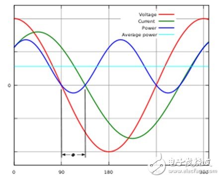
Figure 1. Relationship between AC voltage and AC current for inductive loads
Because pure inductance and pure capacitance do not exist, the actual load can only be called an inductive load or a capacitive load. At this time, there is an angle φ between the AC voltage and the AC current. For inductive loads we call this angle φL, and for capacitive loads it is called φC. (See Figure 2)
AC voltage
AC current of pure capacitive load
AC current of pure inductive load
AC voltage
AC current of actual capacitive load
AC current of actual inductive load
φC
φL

Figure 2. Vector representation of voltage and current for inductive and capacitive loads
Power is equal to the product of voltage and current, but this is only the case when the load is purely resistive (voltage and current are in phase), and when inductive or capacitive loads, the current vector is projected onto the voltage vector (horizontal axis) , Which is to be multiplied by cosφL or cosφC. We usually refer to this cosφL or cosφC as the power factor.
However, because this angle can be positive or negative, the power factor can also be positive (inductive load) or negative (capacitive load).
But when we use vectors to represent voltage and current, the premise is that their frequencies must be exactly the same. And in a linear system.
In a linear system, we will also express the power factor as the ratio of active power to apparent power. The so-called active power is the product of the effective values ​​of the voltage and current in phase with the current. Apparent power is the "power" obtained by directly multiplying the effective values ​​of voltage and current without considering the phase difference therebetween. The ratio of the two is obviously the cosine cosφ of the phase angle mentioned earlier.
Pad Mounted Transformer,Wind Power Substation,Step-Up Wind Power Sustation,Step Up Transformer
Hangzhou Qiantang River Electric Group Co., Ltd.(QRE) , https://www.qretransformer.com