Over the years, manufacturers have been introducing LED lights to the market, with the ultimate goal of replacing incandescent and compact fluorescent lamps (CFLs). The evolution of these bulb designs has ranged from a very simple non-dimmable solution to a high-end but expensive dimming solution to a more cost-effective dimming solution.
Many LED lights claim dimming, but in reality, many LEDs do not perform as well, and their performance varies depending on the dimmer and circuit load used. Sometimes, when the LED light is installed in a room with a dimmer, the LED light will flicker and the brightness cannot be adjusted evenly.
These defects are due to the fact that most of the dimmers used in the United States at this stage are based on two-phase thyristor (TRIAC) two-wire front-end phase-cut circuits developed in the 1960s for resistive incandescent lamps. The TRIAC is a bidirectional semiconductor power switch that is triggered by a pulse generated by a variable timing circuit and remains conductive when the conduction current is higher than the holding current. There are many types of dimmer circuits, using devices with different characteristics and different control circuits and filter components.
The driver circuit of the LED lamp converts the AC input power into a low-voltage DC power supply and maintains a constant current, driving a high-brightness LED load to achieve a constant light output. In order to adjust the basic LED driver circuit through a bidirectional thyristor-based dimmer, additional components must be added to achieve stable dimmer operation and adjust the output current based on the dimmer phase angle.
Due to the large difference in dimmers, the performance of the connected LED dimming circuit is also different. This problem is compounded by the fact that there is no clear standard to classify the performance of LED bulbs with dimmers. At best, some light bulb manufacturers offer a list of dimmers that list the dimmers that they believe are compatible with their products.
With the support of the US Department of Energy (DoE), the National Electrical Manufacturers Association (NEMA) is working on a dimming standard for LED lamps driven by phase-cut dimmers, including test procedures to determine acceptable performance. index. It is hoped that this standard will eventually help to clean up those products on the market that claim dimming, but whose performance is far from the soft, stable, and incandescent dimming expectations that end users expect.
Most LED bulbs use a buck, buck-boost or flyback converter. In each case, acceptable dimming performance can be achieved by modifying the basic circuitry without increasing the cost and complexity of the device. This will improve the performance of the dimmable driver and thus meet the cost savings requirements of the consumer lighting market.
The problem with compatibility is how the TRIAC dimmer circuit interacts with the LED driver input circuitry.
The single-stage LED driver example circuit (Figure 2) replaces the resistive load representing the incandescent lamp in Figure 1. Although this circuit simulates a resistive load due to its high power factor during stable operation, its front end also includes the capacitors necessary for EMI filtering. In addition, LED bulbs consume less than 25% of the equivalent incandescent bulbs. As a result, the dimmer is primarily subjected to capacitive loads during the AC line half cycle before the TRIAC is triggered.
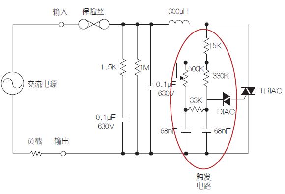
Figure 1: Schematic diagram of a typical dimmer
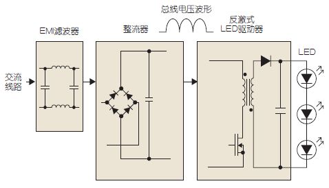
Figure 2: Basic LED Driver Circuit Block Diagram
The bidirectional trigger circuit shown in Figure 1 requires a resistive path to the neutral point if it is intended to operate as designed. If it is changed to a capacitive load, this circuit will not operate normally, and will lead to unstable triggering during periodic conversion, which is manifested by the blinking of the output light. The EMI filter in the dimmer and LED driver also causes ringing oscillations due to the high dv/dt at the start of the TRIAC.
When the amplitude of the oscillation reaches a certain level, it will cause the current to drop below the "hold current", so that the TRIAC is turned off, and the TRIAC cannot be turned on until the next line crosses zero. This condition is usually caused by the trigger circuit re-triggering the TRIAC, causing it to turn on and off multiple times in a single line half cycle. In addition to stressing components and possibly destroying dimmers or LED drivers, this can result in severe flicker and unpleasant noise conditions.
Assuming that the dimmer used for the LED lamp is not an ideal solution to replace the dimmer, the LED driver can be modified to solve the above problem, thereby achieving the use of the LED driver in combination with the standard dimmer.
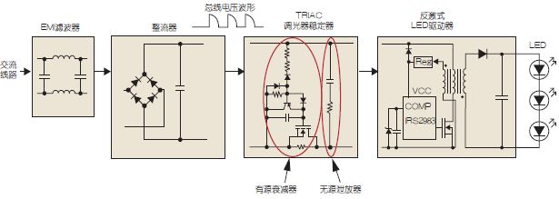
Figure 3: Dimmable LED driver schematic
The example circuit (Figure 3) is a single-stage LED flyback converter, and the same technique can be used for buck-boost or adaptive buck converters. First, the input capacitance must be kept to a minimum when designing the input filter, which also helps achieve the best power factor.
Dimensions
Length: 12.8mm
Width: 5.8mm
Height: 7.5mm (excludes 3mm for terminals)
Arm length: 13.0mm
Features
â—† Small compact Size, high reliability
â—† Micro contact gap,high speed operation,high sensitivity,Micro operatizon travel.
â—† Long life & high reliability
â—† Wide Range of wiring Terminals, Variety of Levers
â—†Mainly used for computer mouse, car mouse, automobile electronic products, communications equipment, military product, test instrument, and general electric and wireless devices, 24 hours timer, etc.
Mushroom Push Button Switch,Subminiature Micro Switch,Miniature Mouse Micro Switch,Ultra Subminiature Micro Switch
Ningbo Jialin Electronics Co.,Ltd , https://www.donghai-switch.com