In this power supply design tip, we will continue to discuss common mode current issues. As mentioned earlier, we can use a rack capacitor to return the common mode current to the power supply, which also reduces the source impedance of the noise. However, there is a safety limit in terms of the size of the capacitor we can use, which determines the remaining amount of the common mode filter. The common mode current is generated by the large AC switching voltage on the drain of Q1 (see Figure 1), which causes current to flow through the stray capacitance into the chassis ground. Rack Capacitor C1 provides a path for returning in the power supply without flowing through the AC input source ground connection. Common mode inductor L1 limits common mode emissions by adding impedance to the path between the power supply frame and the AC input source. At 1 MHz, the maximum allowable inductive reactance of the 4700 pF rack capacitor is 30 Ohms. In order for all the current generated by the switch to enter the rack capacitor C1, this inductor needs to have high impedance (thousands of ohms) in the high frequency range.
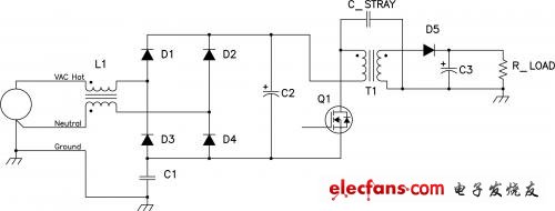
Figure 1. High-impedance common-mode inductor (L1) reduces radiation
Looking further at T2, the inductor is in the hot-wire and neutral-line combination path, and the differential inductor is no longer used to reduce the common-mode current. Many designers use L1 leakage inductance for differential filtering. Due to the inductive connection (shown in Figure 1), there is no net DC current in the inductor, which means that a high permeability, non-gap core can be used. Figure 2 shows the relative permeability of a typical common mode inductor core material versus frequency. In terms of magnetic permeability, there is also a real part and a complex part. The true part is related to the inductance when the repolarization part is related to the material loss. Since the graph is described as a series component, the overall impedance is the vector sum of the two. This is extremely valuable because even if the real part of the inductor starts to attenuate at 300 kHz and cannot be used above 1-2 MHz, the impedance depends on the loss of material above 1 MHz and continues to achieve 10 MHz. high efficiency.
Figure 2 looks for a magnetic core material with a high magnetic permeability margin
Once you have selected the core material, the next biggest challenge is how to make the most of the high magnetic permeability of the core material (see Figure 3), which shows the 28 mH impedance common mode versus frequency. At low frequencies, the device acts like an inductor, but at high frequencies it is more like a distributed capacitor that resonates with the inductor. Due to this large inductance, the 23 pF distributed capacitor affects the performance of the inductor above 200 kHz. The key to designing a high-performance common-mode inductor is to choose a fan-shaped winding, a single winding, and carefully select the core to minimize the number of windings to minimize capacitance. Sometimes these resonances are unavoidable and require additional filtering at higher frequencies. In these cases, we can add another inductor to filter the higher frequencies.
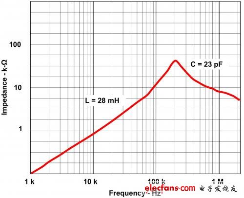
Figure 3 Distributed capacitance reduces common mode inductance impedance
In summary, for high source impedance and safety considerations of noise, common mode filtering of AC power supplies includes several high impedance components to limit capacitance within the rack. Due to the presence of the intermediate winding capacitance, in order to achieve the above functions in terms of high impedance at high frequencies, common mode inductors face great challenges. Care must be taken when selecting the core material, and the material permeability margin must be kept at a high level. In addition, the distributed winding capacitance must be properly controlled. A distributed capacitor of only 30 pF can damage the impedance of the inductor. In most cases, designers will solve this problem by using two inductors in series, each providing filtering in a specific frequency band.
For more details on this article, please see the 2003 Power Design Workshop at www.TI.com/2003powerseminar-ca.
Next time, we will discuss how to select the capacitor in the switch mode power supply, so stay tuned.
For more information on this and other power solutions, please visit http://www.TI.com.cn/lsds/TI_en/analog/powermanagement/power_portal.page.
Toaster, is a commonly used kitchen supplies, mainly used to bake bread. A toaster usually includes a multi-functional oven, a heat-insulating surface, a special lifting device, etc. The more advanced also includes a separable breadcrumb chassis. The toaster is a heating appliance. Its function is to generate enough heat in the vicinity of the bread to bake the bread. If there is no pop-up toaster, breakfast will certainly not be so rich nowadays.
In many families, the toaster is more prone to failure than any other small home appliance. There are two reasons for this. First of all, the toe machine manufacturing costs are generally very low, its quality is not high. You can replace a new device with just $ 10.
Second, the toaster is often not a problem when their own failure, but the food particles interfere with its normal operation. If there are too many slices of bread on the bracket, they will fall into the bottom of the toaster and accumulate when the movement of the tray will move up, thus hindering the movement of the bracket, causing the heating element to short circuit, Open the device and affect the function of the spiral tube.
Most of the pop-up toasters are equipped with a large debris plate and have a door at the bottom, the reason for this. By sliding or opening the broken door, you can clean up the food particles that accumulate at the bottom of the toaster.
Electric Bread Maker,Home Bread Maker,Automatic Bread Maker,Portable Bread Maker
Ningbo APG Machine(appliance)Co.,Ltd , http://www.apgelectrical.com