Related links: Asian enterprise LED bulb design ideas difference analysis [full version]
Before disassembling, first measure the temperature of the LED bulb in the lighted state (Figure 2, Figure 3). The purpose is to confirm whether the difference in the base (heat dissipation) that is significantly different in appearance is reflected in the temperature. The light from the LEDs contains very little infrared light, so the part of the lamp that is illuminated by the light is not too hot. However, the base is the heat sink of the LED chip , so the temperature is high. At this time, a tape having an emissivity of 0.95 was attached to a portion where the base was the hottest (near the mounting position of the LED), and the temperature of the tape was measured by a thermal imager.
Among the 9 LED bulbs, the highest surface temperature of the base is the 7.2W product of Toshiba Lighting Technology (Fig. 2(b)). Comparing in Group A, Samsung LED's 7.1W product is about 47°C, Qinshang Optoelectronic 's 7.5W product is about 43°C, and Toshiba Lighting's 7.2W product is about 61°C, which is higher than these two models. 14 to 18 ° C.
Figure 2: Temperature measurement of LED bulbs in group A (click on image to enlarge)
Note: A tape with an emissivity of 0.95 was attached to the base of the LED bulb, and the temperature of the tape was measured using a thermal imager "TH6300" from NEC Avio Infrared Technology. A tape having an emissivity of 0.95 was used in order to unify the emissivity at the measurement position to 0.95. By measuring the temperature on the tape, an accurate temperature can be obtained. The closer the emissivity is to 1, the better the heat sink will be. In addition, the temperature measurement was assisted by the representative of the Thermal Design Laboratory, Guo Feng Shangshu. The measurement performed after lighting the LED bulb for more than 10 minutes. Toshiba Lighting's 7.2W product has a lower emissivity due to its lower emissivity, but the actual surface temperature is lower, but it is actually as high as 61 °C.
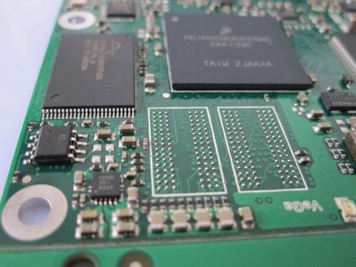
Component Mounting And Soldering.The final step is to mount and solder the components. Both THT and SMT components are placed on the PCB by machines. THT components are most often soldered in an automated process called 'Wave Soldering'. This enables all components to be soldered simultaneously. Their legs are first cut near the board and slightly bent over to keep the component in place. The PCB is then moved over a wave of liquid flux, such that the bottom side strikes the flux. This removes any oxide from the metal surfaces. After heating the PCB it is similarly moved over a wave of melted solder. The solder attaches to the solder pads and component legs, and the soldering is complete.
Component Mounting
Component Mounting,Custom Component Mounting,Metal Component Mounting,Mount Bracket Component
Orilind Limited Company , http://www.orilind.com