In the daily test of engineers, sometimes the results of testing with a multimeter are inconsistent with the results of many high-precision instrument tests. Engineers tend to get confused. Which value is correct? Originally, choosing different measurement modes will The results are very different, this article will analyze the most common four measurement modes, we must be silly and unclear.
Test the same signal, different calculation methods and measurement modes will produce completely different results. The four most commonly used measurement modes include: RMS (true rms also known as rms or rms), MEAN (calibrated to The rectified average of the effective value is also called the corrected average value, DC (simple average value is also called DC component), and RMEAN (rectified average value is also called average value). How to calculate each measurement mode, how to apply, this article will explain in detail.

The true rms value simply means that the AC power is equivalent to the value of the DC power in a unit of time. The true RMS value of 10V AC and 10V DC power are the same for the same load at the same time. . For example, there is a set of 100-volt battery packs that stop for 10 minutes after 10 minutes of power supply (analog of an AC signal). If the battery is driven by a 10Ω Resistor, the generated current I= within 10 minutes of power supply. U/R=10A, power P=U*I=1000W, the current and power are zero when the power is off, then the average power is 500W in 20 minutes. This is equivalent to how much V of DC power is supplied to the 10Ω resistor. By the formula P=U2/R, the voltage U is equal to 70.71V, which is the true rms value of our simulated AC signal.

The theoretical calculation formula for true rms is 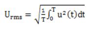 In the instrument measurement, the calculated value is calculated based on the sampling point, so the calculation formula of the true RMS value in the instrument is:
 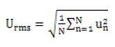 Because the calculation process is squared first, then summed, and finally the root number, so it is also called the root mean square value. It can be seen from the formula that the number of sampling points N directly affects the accuracy of the results. Usually we use the multimeter and power analyzer to test the voltage in RMS mode. For the regular sine wave in the power frequency case, there is almost no difference between the multimeter and the power analyzer test result, but if the voltage signal is not a regular sine wave or frequency comparison When the time is high, the multimeter is limited by the number of sampling points, and the test results will show significant deviations, which is why the variable frequency industry multimeter is not accurate.
For the DC value, it is relatively simple to understand, that is, the DC component contained in the signal to be measured, such as the single-phase power frequency in our daily life, theoretically its DC value is 0, and the DC value is calculated as:  You can switch to Udc mode during the test to see the DC component of the signal.
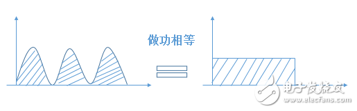
The rectification average means that the area enclosed by the waveform in the same time after full-wave rectification is the same as the area enclosed by the large-value DC signal. Suppose there is an AC voltage with a period of T. After rectification, the area enclosed in one cycle is: 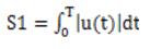 The area enclosed by the DC signal at the same time is: S2=U*T, S1=S2, so the Urmn value is theoretically available:
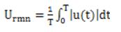
Also in the test instrument, the calculated value is based on the sampling point calculation, and the Urmn value can be obtained:  . The rectified average is used less in normal tests, but its existence has great significance. Why? Let's look at it.
The corrected average is generally used to replace the rms value of the sinusoidal alternating current. According to the sine wave, the form factor is a constant. After measuring the rectified average value, multiplying the form factor to obtain a calibrated average value, which is equal in value to the rms value of the sinusoidal signal. The form factor of the sine wave is  , therefore, the calibration average = * Rectifier average, ie
 , by the formula, the waveform factor is fixed to Therefore, the corrected average value is equal to the effective value only when the measured signal is a sine wave. Conversely, the corrected average value can be considered as the fundamental effective value. Therefore, the Umn value can be used as the fundamental effective value to a certain extent. It is often used in inverters and other occasions. However, it should be emphasized that with the development of technology, the modulation signal is not sinusoidal, and the PWM wave is often a pulse or a square wave. Therefore, only the Umn value is used instead of the fundamental RMS value or there is an error. The best way is to pass the power analyzer. After the FFT operation, the harmonic content is listed and the fundamental data is directly viewed.
Seeing here, the basic concepts of the four voltage modes have been explained. Below we use two actual test data to compare various voltage modes.
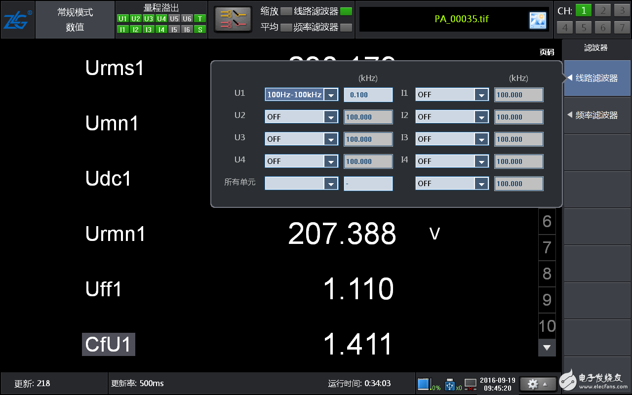
Case 1, testing the grid voltage, in order to get a more standard sine wave to eliminate the influence of harmonics, we added a 100Hz line filter when testing, as shown below:
The test obtained the data of each mode as follows:
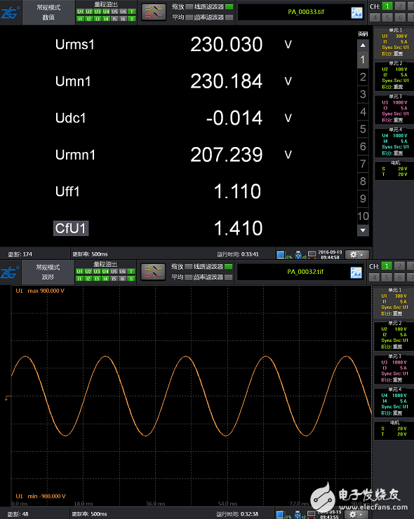
As can be seen from the data, because the sine wave Urms and Umn are very close, Udc≈0, Umn and Urmn are equal to 1.1107≈  In the figure, Cff1 is the waveform factor, Cff1=1.110, which also verifies that the measured signal is a very regular sine wave.
Case 2, test a DC signal and view the voltage data in each mode, as shown below:
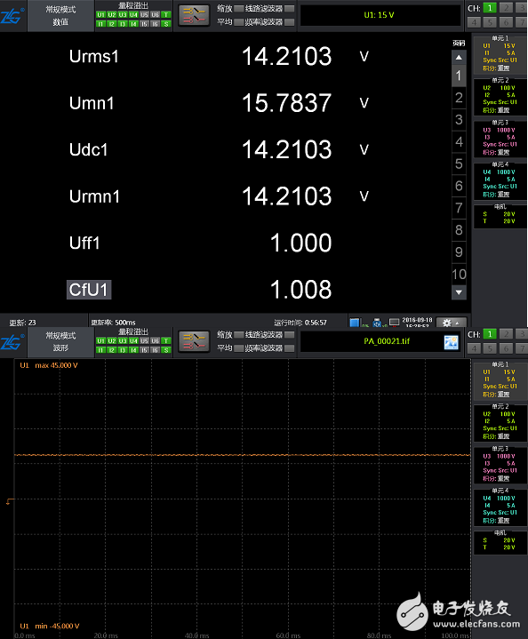
Because it is a DC signal, the values ​​of Urms, Udc, and Urmn obtained by the test are equal, and Umn is calculated by Urmn, so the value of Umn is not equal to Urms. Uff=1.000 can be seen from the figure, indicating that the waveform factor of the DC signal is 1.
Through the above analysis, we know the meaning of the data in different modes, and how to choose the appropriate mode to view the data you need in different situations. The above case data is obtained through the PA series power analyzer test of Zhiyuan Electronics. The PA series power analyzers provide various voltage modes to meet the needs of different customer applications. They are suitable for measurement and testing of various power applications and have been obtained by users at home and abroad. widely accepted.
Film capacitors are electrical capacitors with an insulating plastic film as the dielectric, sometimes combined with paper as carrier of the electrodes. These plastic films are sometimes metalized and are available in the market under the name metalized film capacitor,these capacitors are sometimes also called plastic capacitors.
Film Capacitor,X-Ray equipment Capacitor,Axial Polyester Capacitor,Polypropylene High Voltage Capacitor
XIAN STATE IMPORT & EXPORT CORP. , https://www.capacitorhv.com