With the continuous development of human society, the energy issue has increasingly become a major problem facing all countries. Finding “clean†new energy sources and saving energy and consumption will become the eternal theme of human society development. Urban lighting electricity consumption is a major consumer of electric energy, so it is of great significance to study urban lighting power-saving technology.
In the lighting power supply system, especially in the street lamp power supply line, in order to avoid the line loss during the power transmission process and the terminal voltage caused by the peak of power consumption is too low, the situation that the street light is not bright is often caused by The high voltage transmission exceeds the rated voltage of the consumer. Moreover, since the lighting electricity consumption time is mostly in the night grid trough section, the power supply voltage tends to be high, and at this time, the traffic flow on the road is small, which inevitably leads to an increase in the luminous flux of the street lamp and an increase in the road surface illumination. This not only wastes electrical energy, but also seriously affects the service life of the lighting fixture. Therefore, the working principle of the lighting power saving device is mainly to stabilize or appropriately reduce the power supply voltage. Taking the most commonly used 250W high-pressure sodium lamp as an example, there is information that the 200 V is the optimum supply voltage for the midnight light. At this time, the current is reduced by 6.3%, the power saving rate is 16.1%, and the power can be extended by one time. Lamp life and reduce maintenance costs.
On the whole, there are two types of technical means: one is the voltage regulating and step-down method with the AC transformer as the core, including multi-tap, auto-coupling, etc., but it is bulky, bulky, with low adjustment precision or level adjustment. Disadvantages such as poor reliability; another type of static voltage regulator with power electronics as the core, among which the voltage regulator using thyristor phase-controlled voltage regulation has been widely used, but due to the phase control method, there are low power factor and large harmonics. Shortcomings such as slow dynamic response and large filter size.
With the development of power electronics technology and microelectronic technology, AC chopper technology (also called matrix converter [3]) has become a mature means of AC voltage regulation, and can be widely used in lighting, motor drag, industrial heating and other fields. This technology has the advantages of only relying on the power factor of the load, fast dynamic response, wide linear voltage regulation range, and easy filtering of input and output.
Based on the analysis of AC chopping technology, this paper designs a small-phase, easy-to-use and efficient single-phase AC chopper lighting power saver, and verifies the feasibility of the scheme through simulation and experiment.
1 Principle of AC chopping technology
Figure 1 is a schematic diagram of the principle of a single-phase AC chopper main circuit.

Figure 1 Schematic diagram of single-phase AC chopping main circuit
In the ideal chopping mode, the chopper switches S1, S2 and the freewheeling switches S3, S4 operate alternately, and each switching cycle is divided into a æ–© waveguide pass and a freewheeling conduction phase. The output voltage is
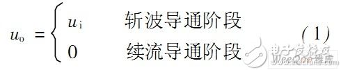
Ui-- input power supply voltage
Ui=Umsinωt
Um—the input voltage peak
ω———Input voltage angular frequency
Fourier analysis of uo

Ωc———Chopping Frequency D———Duty Cycle
It can be seen from equation (3) that by changing the duty ratio D, the fundamental amplitude can be changed and in a linear relationship. At the same time, the output voltage uo contains only the higher harmonics of the chopper switching frequency except the fundamental wave, which is easy to filter out. When the switching frequency is high enough, as long as a smaller size input and output filter is introduced, the harmonics in the input current and output voltage can be completely filtered without changing the power factor of the system.
Therefore, the lighting power saver using the AC chopper technology can reduce the device volume and improve the power factor.
2 AC chopper voltage control technology
The AC chopper voltage regulation control method is related to the working mode of the switching device, and is generally divided into complementary control and non-complementary control. Among them, S1~S4 are full-control switches, which are generally replaced by IGBT units with anti-parallel diodes. S1 and S2 act as chopping waves, and S3 and S4 act as freewheeling.
2. 1 Complementary control method
The complementary control mode means that the chopper switch and the freewheeling switch must have one and only one conduction during one switching cycle, and the driving signal is required to be strictly accurate. Since the power electronic device needs to be turned on and off for a certain period of time, the switch-through phenomenon will occur during the transition phase without processing. Therefore, in practice, a dead zone must be added between the two control signals, that is, two types of switches during the transition period. Shut down at the same time. However, due to the existence of the dead zone, the inductive circuit is likely to cause a large transient voltage shock, and a buffer circuit with a certain power needs to be added. This not only makes the waveform distortion, but also reduces the efficiency, and the design of the snubber circuit is also difficult.
2. 2 non-complementary control method
The non-complementary control mode refers to controlling the working state of the chopper switch and the freewheeling switch according to different laws, so as to avoid the short circuit phenomenon caused by the straight-through in the complementary control, and it is not necessary or only a small buffer circuit is needed. According to the detection of load current or not, it is divided into two types: no current detection and current detection.
Non-current detection non-complementary control can avoid straight-through phenomenon. However, when the input voltage and the output current are out of phase, the control mode is out of control, that is, the output voltage is not a chopping waveform. The presence of the runaway zone causes the output voltage to contain significant 3rd and 5th harmonics. In the case of non-complementary control mode with current detection, when the voltage and current are out of phase, the freewheeling switch also performs chopping operation, which eliminates the runaway phenomenon, but the control is more complicated.
3 new AC chopper lighting saver
In this paper, a new type of AC chopper lighting power saver is designed. The topology diagram is shown in Figure 2(a). The chopper switch uses only one switch tube to connect across the bridge diode rectification ends. The AC chopping scheme adopts a non-complementary control mode, and its control waveform diagram is as shown in Fig. 2(b). Where ui is the input voltage and io is the output current. S0 and S1, S2 represent the drive signals of the three switch tubes, respectively. In this control mode, only one switch tube operates in a chopping state, the cost is reduced, the switching loss is reduced, and the control is simple, easy to implement, and high in reliability.
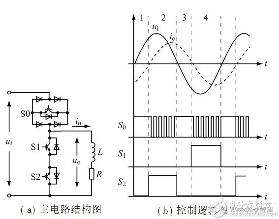
Figure 2 Three-switch AC ripple
A duty cycle can be divided into four intervals according to the phase relationship between the input voltage and the output current. The working state of the switch tubes in each section is shown in Table 1.
Table 1 Switch tube working status
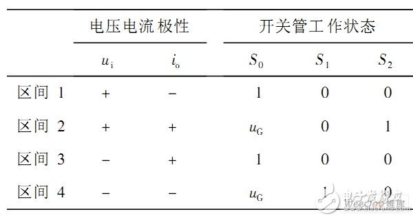
Note: 1 indicates that the switch is conducting, 0 indicates shutdown, and uG indicates chopping operation.
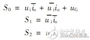
The above state can also be expressed by the following logical expression:
3. 1 logic circuit control method
It is implemented according to the logic circuit shown in FIG.
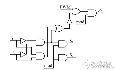
Figure 3 logic circuit schematic
The switching signals S0, S1 and S2 respectively control the corresponding three switching tubes; mod is the working mode switch, which works normally when the high level is high, and prohibits the operation when the level is low; i and u are the detection current and the voltage phase for the logic judgment.
3. 2 Simulation analysis
According to the above control principle, the simulation model is built using the Simu-link toolbox in MATLAB. The power supply voltage is AC. Figure 3 Logic circuit schematic diagram 220 V, 50 Hz, load L is 0. 5 H, R is 200 Ω, switching frequency is 5 kHz, duty cycle D is 0. 6. Output voltage uo waveform and different The output voltage total harmonic distortion rate THDU at the air ratio is shown in Figures 4 and 5, respectively. When the output side is filtered with an inductor of 0.83 mH and a filter capacitor of 12 μF, the total harmonic distortion rate THDU of the output voltage at different duty cycles is shown in Fig. 6.
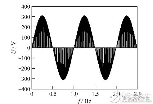
Figure 4 Pure resistive load output voltage uo waveform diagram (the horizontal coordinate represents 50 Hz per small grid)
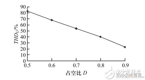
Figure 5 Pure resistive load duty cycle D and THDU diagram
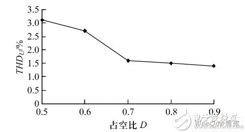
Figure 6 Diagram of duty cycle D and THDU with output filter
As can be seen from Figures 4 to 6, the total harmonic distortion rate THDU is related to the duty cycle. And as the duty cycle D increases, the harmonics are significantly reduced, and after the output filtering, the THDU is smaller. For the lighting power saver, the operating voltage of the ideal power-saving mode is about 200 V, and the upper limit of the fluctuation of the 220 V supply voltage is ±20%, and the duty ratio D is at a minimum of 0.83. Therefore, the harmonic effect generated by the actual operation of the control mode is small.
3. 3 test data and analysis
The specific parameters of the circuit constructed according to the above basic principles are as follows: power supply voltage 220 V, 50 Hz, isolation transformer 300 VA, resistive load 200 Ω, series 0. 5 H inductance, switching frequency 5 kHz. Figure 7 shows the output voltage uo waveform, Figure 8 shows the relationship between the duty cycle and the output voltage total harmonic distortion rate THDU. Figure 9 shows the duty cycle and output voltage when the output filter inductor is 0.83 mH and the filter capacitor is 12 μF. The relationship of the total harmonic distortion rate THDU. The above curve shows that as the duty cycle D increases, the total harmonic distortion rate THDU of the output voltage gradually decreases, which is consistent with the simulation results.
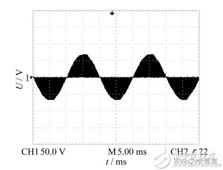
Figure 7 Pure resistive load output voltage uo waveform (5 ms for each sub-area and 50 V for each ordinate)
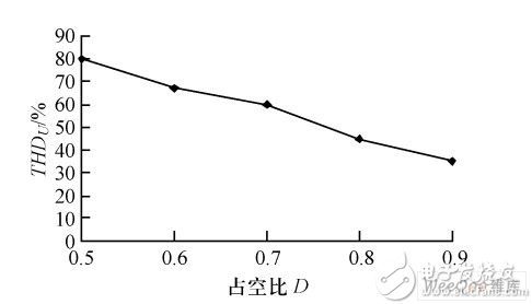
Figure 8 Resistive load duty cycle D and THDU diagram
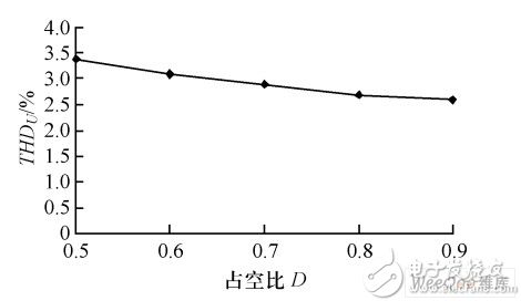
Figure 9 Diagram of duty cycle D and THDU with output filter
And with the output filtering, the total harmonic distortion rate THDU is smaller, which can meet the actual needs.
3. 4 characteristics of lighting saver
The lighting power saver made according to the above principle can be applied to lighting fixtures such as incandescent lamps, fluorescent lamps, gas discharge lamps (including high-pressure mercury lamps, high-pressure sodium lamps and metal halides), and thus is widely used and has the following working characteristics:
(1) Easy to install, no need to change the original lighting distribution line.
(2) All solid-state devices, no contacts, taps, etc., maintenance-free, while eliminating the transformer, so small size and high efficiency.
(3) With the microprocessor as the control core, the power saver can work in the preset power-saving operation mode, and can also be combined with the remote communication technology to realize remote control and is easy to use.
(4) The protection circuit can monitor the actual running state of the power saver in real time. If there is a serious abnormality, an alarm can be provided and the device can be bypassed, which does not affect the normal power supply of the lighting, but does not provide a power-saving operation mode.
(5) Using this working principle, it can also be made into a three-phase circuit for high-power applications, and a compensation-type structure can also be used to improve the working efficiency of the device.
4 Conclusion
This paper designs a lighting saver based on AC chopping technology. The power saver adopts a three-switch tube topology structure, has a simple structure, small loss, convenient control and high reliability. The lighting energy-saving equipment with this technology as the core represents the future development direction, and has broad application prospects in the power saving of lighting fixtures.
LANA Vape Pen 2000 Puffs is so convenient, portable, and small volume, you just need to take them out of your pocket and take a puff,
feel the cloud of smoke, and the fragrance of fruit surrounding you. It's so great.
We are China leading manufacturer and supplier of Disposable Vapes puff bars, lana vape pen 2000 puffs disposable,lana vape pen 2000 puffs kit,
lana vape pen 2000 puffs plus, and e-cigarette kit, and we specialize in disposable vapes, e-cigarette vape pens, e-cigarette kits, etc.
lana vape pen 2000 puffs disposable,lana vape pen 2000 puffs kit,lana vape pen 2000 puffs plus,lana vape pen 2000 puffs rechargeable, lana vape pen 2000 puffs e-cigarette
Ningbo Autrends International Trade Co.,Ltd. , https://www.vapee-cigarettes.com