The half-bridge power conversion circuit is a widely used topology in power electronics, designed to overcome the imbalance issues found in push-pull configurations without increasing overall circuit complexity. This configuration is particularly effective in applications where efficiency and reliability are key considerations.
As shown in the figure, the half-bridge circuit consists of two power transistors, V1 and V2, connected in series with two capacitors, C1 and C2. The primary winding of the transformer is connected between the midpoint of these capacitors and the output side. Due to the voltage division effect of the capacitors, the voltage at this midpoint is approximately half of the input DC voltage, making it a stable reference point for the circuit.
The other end of the primary winding is connected through a capacitor, C3, to the emitter of V1 and the collector of V2. When V1 is turned on, the primary side of the transformer experiences a voltage pulse of about +Ui/2. Conversely, when V2 is activated, the voltage becomes approximately -Ui/2. This alternating switching generates a square wave with a peak-to-peak voltage of around Ui across the primary winding of the transformer.
This design significantly reduces the maximum voltage that each transistor must withstand compared to a traditional push-pull circuit. Specifically, the maximum voltage rating required for the transistors is only half of what is needed in a push-pull setup. However, it's important to note that while the voltage stress is reduced, the current through the transistors may increase under the same power output conditions. This trade-off should be carefully considered during the design phase to ensure optimal performance and component selection.
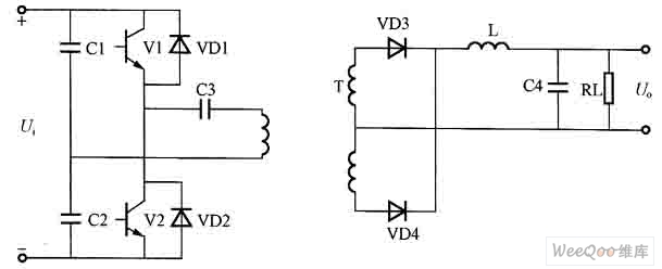
Figure: Half Bridge Power Conversion Circuit
NEA Standards are guidelines from the National Electrical Manufacturers Association (NEA) for the design and construction of utility poles used to support power lines. These standards outline the material, size, strength and installation requirements for utility poles to ensure that they carry power infrastructure safely and reliably. Poles that meet NEA standards are typically made of wood, steel, or concrete and can withstand a variety of environmental conditions and loads.
Nea Standard Pole,Electric Power Transmission Pole,Steel Transmission Pole,Distribution Transmission Pole
JIANGSU HONGGUANG STEEL POLE CO., LTD. , https://www.hgsteelpoles.com