The half-bridge power conversion circuit is a widely used topology in power electronics, offering an efficient solution to the imbalance issues often found in push-pull configurations without increasing circuit complexity. This design uses two switches—typically transistors—to control the flow of power through the primary winding of a transformer. As shown in the diagram, one end of the primary winding is connected to the midpoint between two series capacitors, C1 and C2. Due to the voltage division effect, this point maintains approximately half of the input DC voltage. The other end of the transformer is connected to the emitter of transistor V1 and the collector of V2 via capacitor C3.
When V1 is turned on, this point becomes connected to the positive terminal of the input bus, generating a voltage pulse of around +Ui/2. Conversely, when V2 is activated, it connects to the negative terminal, producing a pulse of approximately -Ui/2. By alternating the switching of these transistors, a square wave with a peak-to-peak voltage of about Ui is created on the primary side of the transformer. This configuration significantly reduces the maximum voltage stress on each transistor compared to a push-pull setup, as they only need to handle half the input voltage.
However, there's a trade-off. While the primary voltage is halved, the current through the transistors increases under the same output power conditions. This means that careful thermal management and component selection are essential to ensure reliable operation. The half-bridge circuit is particularly useful in applications where efficiency and simplicity are key, such as in switch-mode power supplies, motor drives, and renewable energy systems.
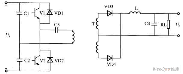
Figure: Half Bridge Power Conversion Circuit
Electric pole, also known as a telephone pole or telegraph pole, is a tall structure used to support overhead power lines and other utilities, such as telephone and cable lines. These poles, typically made of wood, metal or concrete, are installed along roadsides, in residential and rural areas to deliver electricity and other services to homes and businesses. The height and design of poles can vary depending on the specific requirements of the utility company and the location of the poles.
Electric Pole,Distribution Steel Pole,Utility Pole,Electricity Pole
JIANGSU HONGGUANG STEEL POLE CO., LTD. , https://www.hgsteelpoles.com