Class D amplifiers were first proposed in 1958 and have become popular in recent years. So what is a Class D amplifier? How do they compare to other types of amplifiers? Why do Class D amplifiers make sense for audio applications? What factors need to be considered when designing a “good†Class D audio amplifier? This article attempts to answer all of the above questions.
Audio amplifier background
The purpose of the audio amplifier is to reproduce the true, efficient and low distortion input audio signal on the vocal output component at the required volume and power level. The audio frequency range is approximately 20 Hz to 20 kHz, so the amplifier must have a good frequency response over this frequency range (the frequency range is reduced when driving a speaker with a limited band, for example, a woofer or tweeter). Output power capability varies widely depending on the application, from milliwatts (mW) of headphones, several watts (W) of TV (TV) or personal computer (PC) audio, tens of watts of "mini" home audio and cars Audio, home and commercial audio systems with high powers of hundreds of watts and hundreds of watts, and theater or concert hall sound systems.
A direct analog implementation of an audio amplifier uses a transistor to produce an output voltage proportional to the input voltage in a linear mode of operation. The forward voltage gain is typically very high (at least 40 dB). If the forward gain is part of the feedback loop, then the total loop gain will also be high. Feedback loops are often used because high loop gain improves performance, rejects distortion due to linearity errors in the forward path, and reduces power supply noise by increasing power supply rejection (PSR).
Advantages of Class D amplifiers
In conventional transistor amplifiers, the output stage contains transistors that provide instantaneous continuous output current. Many possible types of audio system amplifiers are available, including Class A amplifiers, Class AB amplifiers, and Class B amplifiers. Compared to Class D amplifier designs, even the most efficient linear output stage, their output stage consumes a lot of power. This difference makes Class D amplifiers a significant advantage in many applications because low power generates less heat, saves printed circuit board (PCB) area and cost, and extends battery life in portable systems.
Linear amplifier, class D amplifier, and power dissipation
The linear amplifier output stage is connected directly to the speaker (in some cases via a capacitor). If the output stage uses bipolar junction transistors (BJTs), they typically operate in a linear fashion with large collector voltages. The output stage can also be implemented with a complementary metal oxide semiconductor (CMOS) transistor, as shown in Figure 1.
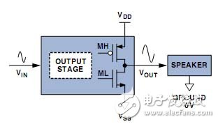
Figure 1. CMOS linear output stage
Power consumption is at all linear output stages because the process of generating the output voltage VOUT inevitably results in non-zero IDS and VDS in at least one of the output transistors. The amount of power consumed depends primarily on the biasing method on the output transistors.
Class A amplifier topologies use a single transistor as a direct current (DC) current source that provides the maximum audio current required by the speaker. Class A amplifier output stage can provide excellent sound quality, but the power consumption is very large, because usually there is a large DC bias current flowing through the output stage transistor (which we do not expect), but not provided to the speaker (this is us Expected).
Class B amplifier topologies have no DC bias current, so power consumption is greatly reduced. Its output transistors are independently controlled by push-pull, allowing the high-side transistors to supply positive current to the speaker and the low-side transistors to sink negative current. Since only the signal current flows through the transistor, the output stage power consumption is reduced. However, the quality of the Class B amplifier circuit is poor because it causes a linearity error (crossover distortion) when the output current crosses zero and the transistor switches between on and off states.
Class AB amplifiers are a combination of Class A and Class B amplifiers. They also use DC bias current, but they are much smaller than pure Class A amplifiers. The small DC bias current is sufficient to prevent crossover distortion and thus provide good sound quality. Its power consumption is between Class A and Class B amplifiers, but is usually closer to Class B amplifiers. Similar to Class B amplifier circuits, Class AB amplifiers also require some control circuitry to provide or sink large output currents.
Unfortunately, even a well-designed Class AB amplifier consumes a lot of power because the output voltage in the range is usually far from the positive or negative supply. Since the voltage drop between the drain and source is large, a large instantaneous power consumption IDS & TImes; VDS is generated.
Class D amplifiers have much lower power consumption than any of the above types of amplifiers due to their different topologies (see Figure 2). The output stage of the Class D amplifier switches between a positive supply and a negative supply to generate a series of voltage pulses. This type of waveform helps to reduce power consumption because the output transistor has zero current when it is not conducting, and has a very low VDS when turned on, resulting in a smaller power consumption IDS & TImes; VDS.
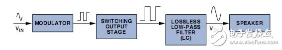
Figure 2. Block Diagram of a Class D Open Loop Amplifier
Since most audio signals are not bursts, a modulator must be included to convert the audio input into a pulsed signal. The frequency components of the pulse include the desired audio signal and the important high frequency energy associated with the modulation process. A low pass filter is often inserted between the output stage and the speaker to minimize electromagnetic interference (EMI) and to avoid driving the speaker with too much high frequency energy. In order to maintain the power consumption advantages of the switching output stage, the filter (see Figure 3) is required to be lossless (or nearly lossless). Low-pass filters typically use capacitors and inductors, and only the speaker is an energy-consuming component.
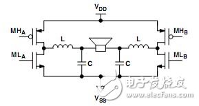
Figure 3. Differential Switch Output Stage and LC Low Pass Filter
Figure 4 compares the ideal value of the Class A and Class B amplifier output stage power dissipation (PDISS) with the measured value of the AD1994 Class D amplifier output stage power dissipation. The curve in the figure refers to the relationship between the output stage power of a given audio sine wave signal and the load power (PLOAD) provided by the speaker. The load power is normalized to the maximum load (PLOAD max) power level, and the clamped sine wave signal guarantees 10% total harmonic distortion (THD). The vertical line in the figure indicates where PLOAD begins to clamp.
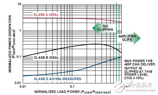
Figure 4. Power Comparison of the Output Stages of Class A, Class B, and Class D Amplifiers
It can be seen that the power consumption is significantly different for a variety of loads, especially at high end and mid-range load conditions. At the beginning of the clamp, the Class D amplifier output stage consumes approximately 1/2.5 of the Class B amplifier and is 1/27 of the Class A amplifier. It should be noted that the power consumed in the output stage of the Class A amplifier is greater than the power delivered to the speaker, which is the result of using a large DC bias current.
The output stage power efficiency Eff is defined as follows:
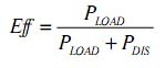
At the beginning of the clamp, the Eff of the Class A amplifier is 25%, the Eff of the Class B amplifier is 78.5%, and the Eff of the Class D amplifier is 90% (see Figure 5). These best examples are often cited in textbooks for Class A and Class B amplifiers.
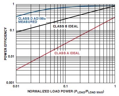
Figure 5. Power efficiency comparison of Class A, Class B, and Class D amplifier output stages
The difference in power consumption and power efficiency is large at medium power levels. This is important for audio because the long-term average power level of loud music is much lower than the instantaneous peak level of PLOAD max (1/5 to 1/20, depending on the type of music). Thus, for an audio amplifier, [PLOAD = 0.1 & TImes; PLOAD max] is a reasonable average power level at which PDISS is evaluated. At this power level, the power dissipation of the Class D amplifier output stage is 1/9 of that of a Class B amplifier and 1/107 of a Class A amplifier.
For Fire Extinguisher Use, Drop the auto fire extinguisher ball to extinguishing the fire.
Fire Extinguisher Drone,Drone Fire Extinguisher,Forest Firefighting Drones,Drone For Fire Department Use
shenzhen GC Electronics Co.,Ltd. , https://www.jmrdrone.com